A Simple Curve Tracer
Simple Curve Tracer Circuit
In order to test components such as diodes but also to identify nonlinear behaviour of inductive components, a simple curve tracer was built. (Thanks to techlib.com for the inspiration!)
(Click images to enlarge)
Circuit description
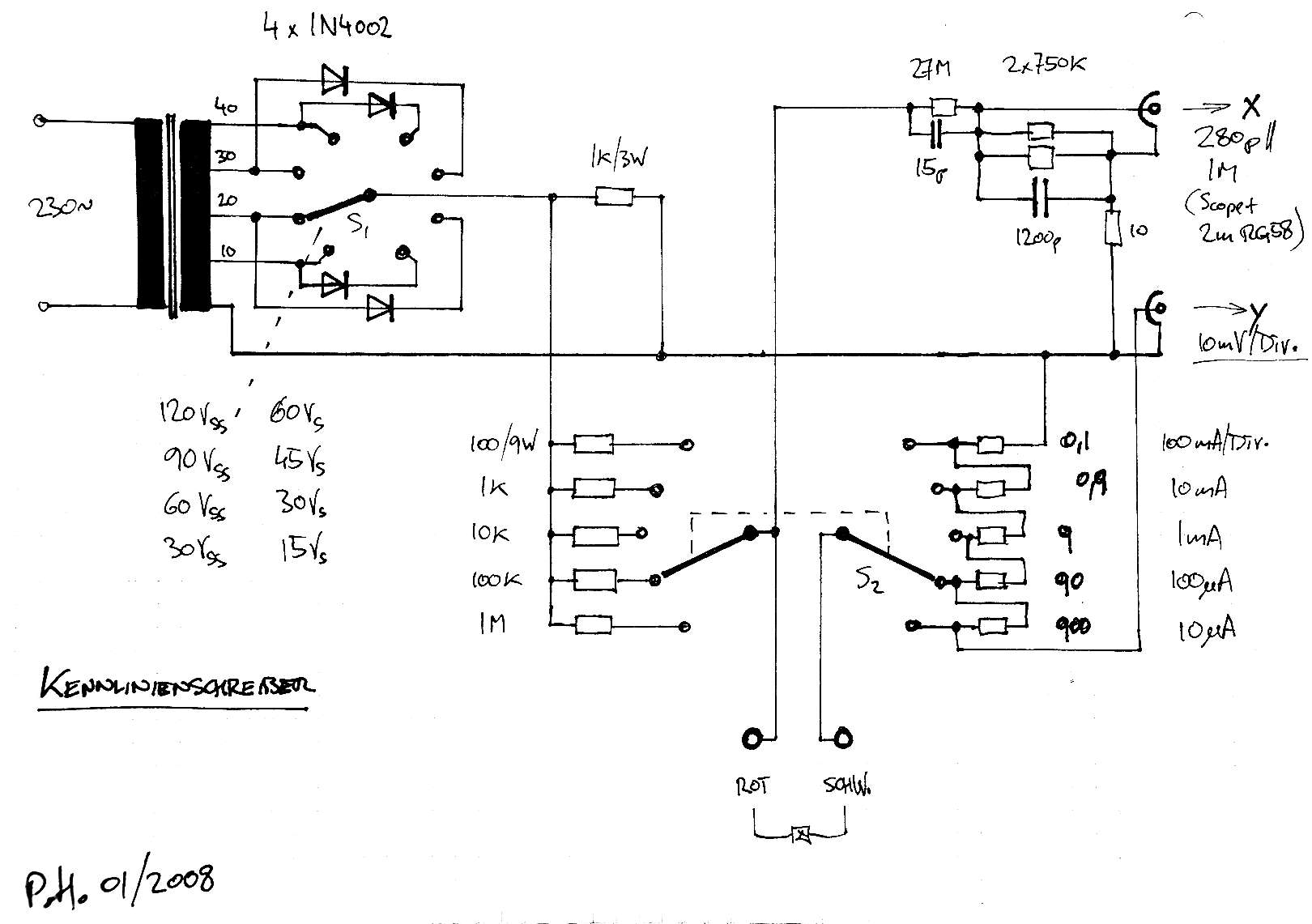
For a display, the unit uses a standard oscilloscope in X-Y mode (with 1 Ω || 10 pF) inputs,
connected via two 2 m RG58 cables.
The voltage across the DUT is divided 100:1 so that a 0.1 V/div setting on the scope will yield a 10 V/div scaling. The divider is compensated for the combined input capacity of the scope and connecting cable (approx. 280 pF).
Two rotary switches are provided to select peak voltage and current ranges. The voltage switch is wired with diodes so that for each voltage, either symmetrical AC or positive-only half waves can be selected.
For the current ranges, both the current limiting resistors and the current sensing resistors are switched; with the oscilloscope Y channel set to 10 mV/div, this yields five ranges from 10 µA to 100 mA/div. In the sample, resistors in 900/90/9 etc. Ohms values were available that were connected in series. Of course it is also possible to use 1K/100/10 etc. Ohms conencted from each switch contact to ground.
CAUTION: These instructions are for experts ONLY. The circuit is connected to mains voltage, which can kill if handled improperly. Incorrect wiring may also create a fire hazard! It is of course self-evident that mains voltage and all inputs must be disconnected completely before opening the case!
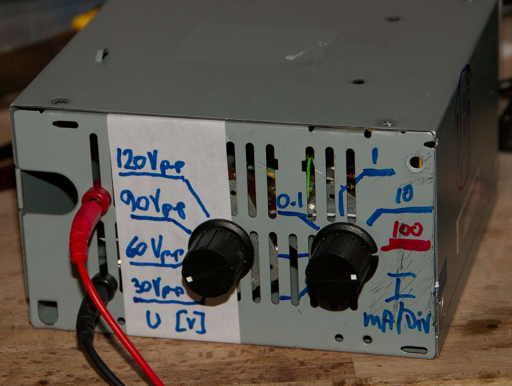
Sample in ATX Power Supply case
The sample unit was built into the case of an old ATX PC power supply.
The transformer in the sample is from a late-1980s CD player and happened to have four convenient 10 V windings in series.
A similar 4 × 9 V (or two cheap 2 × 9 V) units, or any other combination of voltages that satisfy your needs can be used as well.
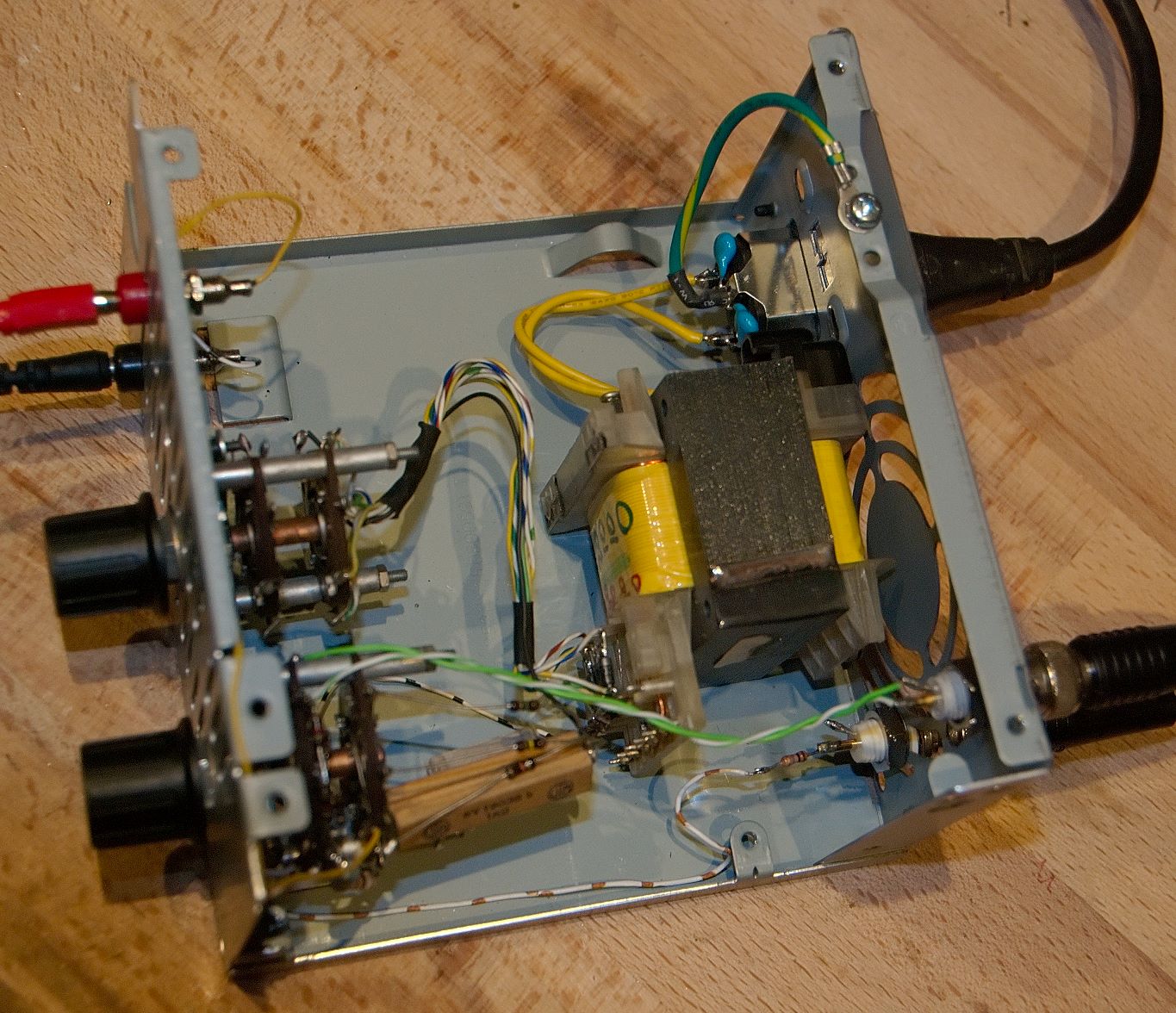
Internal view
Care must of course be taken so that sensitive components are not overloaded. The 100 mA/div range in particular should be used with caution.
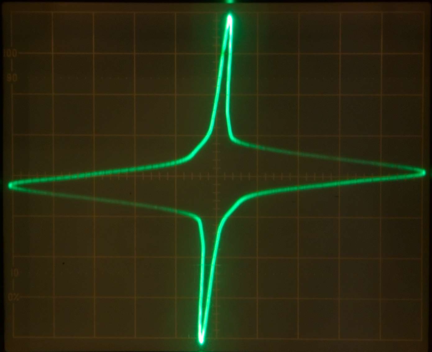
Sample: Dual filter choke (2 × 33 mH) - nonlinearity increasing with current
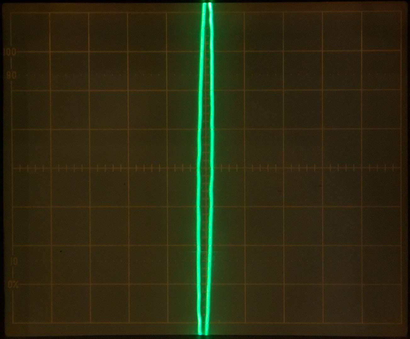
1 mA / div
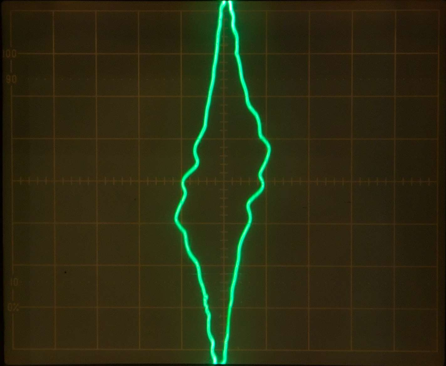
10 mA / div
100 mA / div
10 mA / div
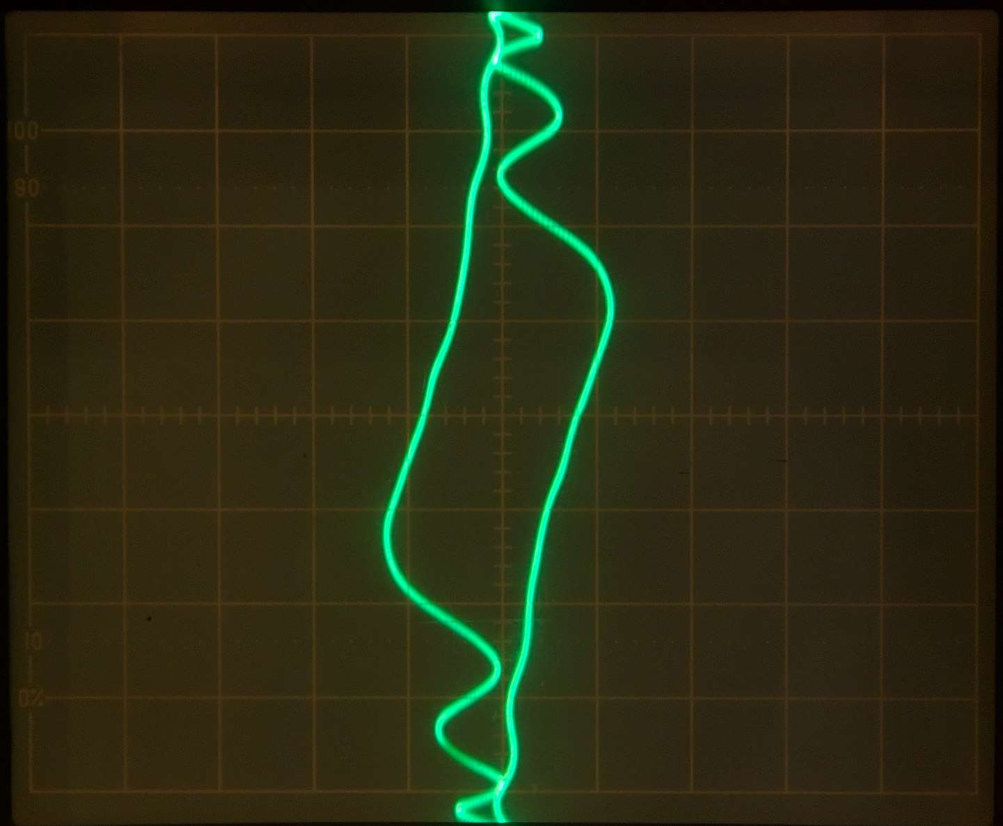
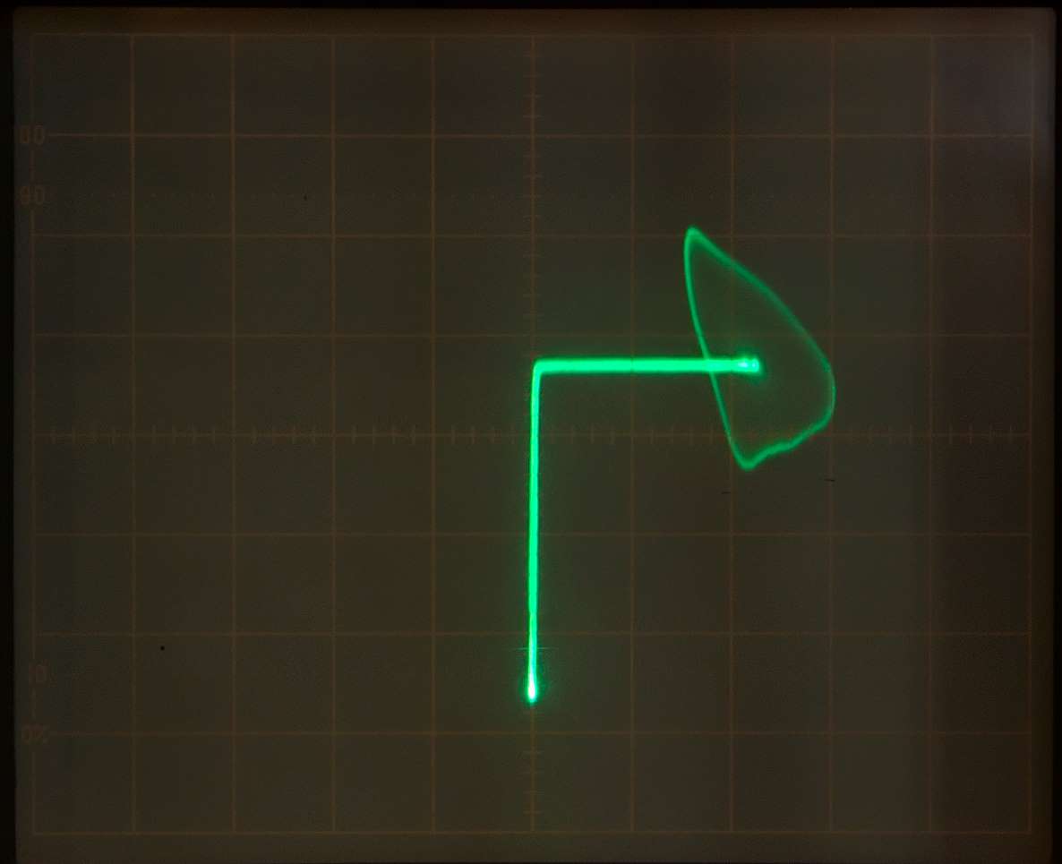
Same choke in parallel
with a 2.2 µF capacitor
Notice resonant oscillations triggered by coil nonlinearity at high currents
100 mA / div
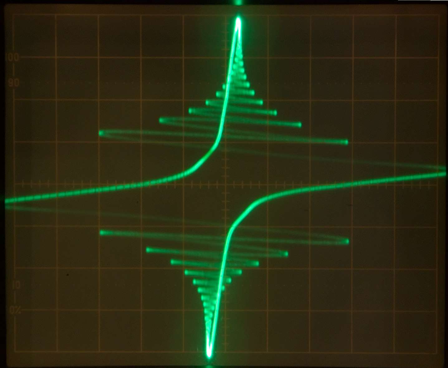
Left: IRF540 MOSFET UD-S vs. ID
at gate voltage (UG-S) = +4 V
without gate resistance (notice oscillation)