Solartron 7150 / 7150plus Multimeter
Solartron 7150+ Multimeter
(click images to enlarge)
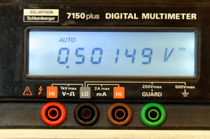
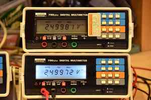
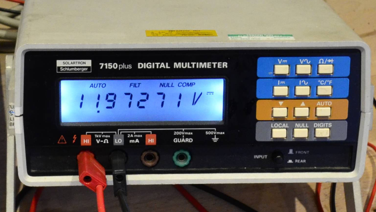
The Solartron Schlumberger 7150plus is a compact bench/portable, mains-operated multimeter, similar to the popular HP/Agilent 34401A, which offers 5½ / 6½ digits resolution (2.350.000 counts max) and an accuracy to 0.005%. (The meter displays a walking average of readings in the 6½ digit mode, increasing resolution but not accuracy.)
The 7150plus includes a n IEEE488 bus interface as a standard feature, has switchable front/rear inputs, four-wire ohms measurement (rear input only), a temperature range for external PT100 sensors, "True" RMS converter in the AC ranges, and an input resistance of > 10 GΩ in the low DC ranges (0.2/2 V). A key limitation is that there is only a single current range (2 A), also the Ohms ranges go down only to 2 kΩ. The inputs are simple 4 mm banana jacks, not the newer type allowing for safety plugs.
The 71xx family was introduced in the mid-1980s. The predecessor, the 7150 (without "plus") lacks the temperature range (and 6½-digit averaging mode IIRC) but is otherwise almost identical. There is also a similar model 7151 which additionally contains math capabilities, an RS-232 serial port, and an 8-bit D/A output that can be used to connect a recorder, or to view the last 100 readings on an oscilloscope.
Some years ago, a large quantity of 7150 series meters from NATO surplus hit the second-hand test gear market, making it readily available at an affordable price. Some even came with the original leather carrying cases including probe sets. Didier (KO4BB) has copies of the Solartron 7150 plus user and service manuals as well as the EPROM images in his amazing online collection of manuals.
Inside
The meter is built in good quality 1980s technology (all through-hole components) on a motherboard ("earthy logic") carrying power supply, processor, IEEE488 (HPIB, GPIB) interface and a display board, plus a galvanically isolated, separate analog/floating logic board with its own processor controlling the A/D conversion and communicating serially with the base unit. The two boards are separated by an aluminium shield/chassis.
The main CPU is a Motorola/Hitachi HD6303 with a 16k EPROM (27128) and 2k RAM (5516). There is space for a second RAM socket in the board layout for an MC68A10 RAM (128 × 8) "if fitted" —why would one, though? The IEEE488 interface is a fixed part of the main board and uses the standard Motorola MC68488 controller with two MC3447 buffers.

Digital motherboard ("earthy logic") and display
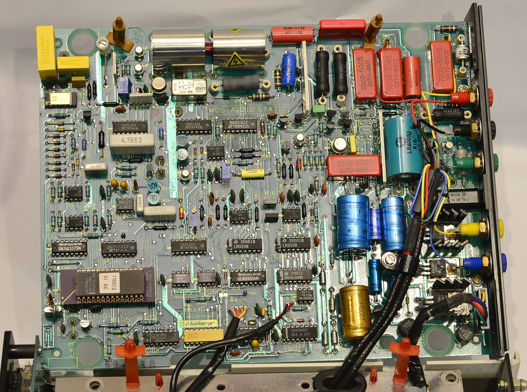
Analog board ("analog / floating logic") with rear input jacks
The microcontroller on the analog board is a 6801 type. In some instruments, like in the one shown here, a HD68P01M with piggy-back EPROM (2764) would be used, while a Hitachi HD637B01 with internal EPROM can be found in others.
The A/D converter is built using individual op-amps (OP05, OP14 etc), FETs and analog switches (mostly DG211). The RMS converter is a standard Analog Devices type AD637, allowing a specification to 100 kHz.
A little surprise may be the choice of voltage reference, here we find a (possibly selected) 1N829A precision, temperature-compensated Zener diode with approximately 6.2 Volts. The actual voltage may be from 5.9 to 6.5 V and is neither trimmed nor is it critical, soft calibration will take care of that — only stability counts, and in this regard, the good old 1N829 features a very respectable TC of 5 ppm/°C.
A careful observer will note a cute detail in the diagram and on the analog board: The single "star" grounding point is labelled "ROME" — all roads, er, grounds lead there, after all ...
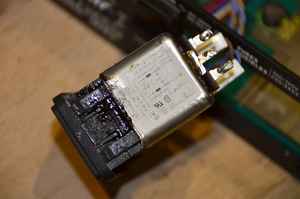
Like all Solartron meters of the era, this one is software calibrated. To enable calibration, a plug must be inserted on the rear that physically enables the Vpp supply (-25 V!) to the pair of NCR7033 "EAROMs" (serial EEPROMs with 21 × 16 bits) located on the analog board. This placement allows analog and digital boards to be replaced individually without loss of calibration). Soft calibration can be intiated either over the GPIB or from the keyboard.