Weston 155 AC Voltmeter, ca. 1922
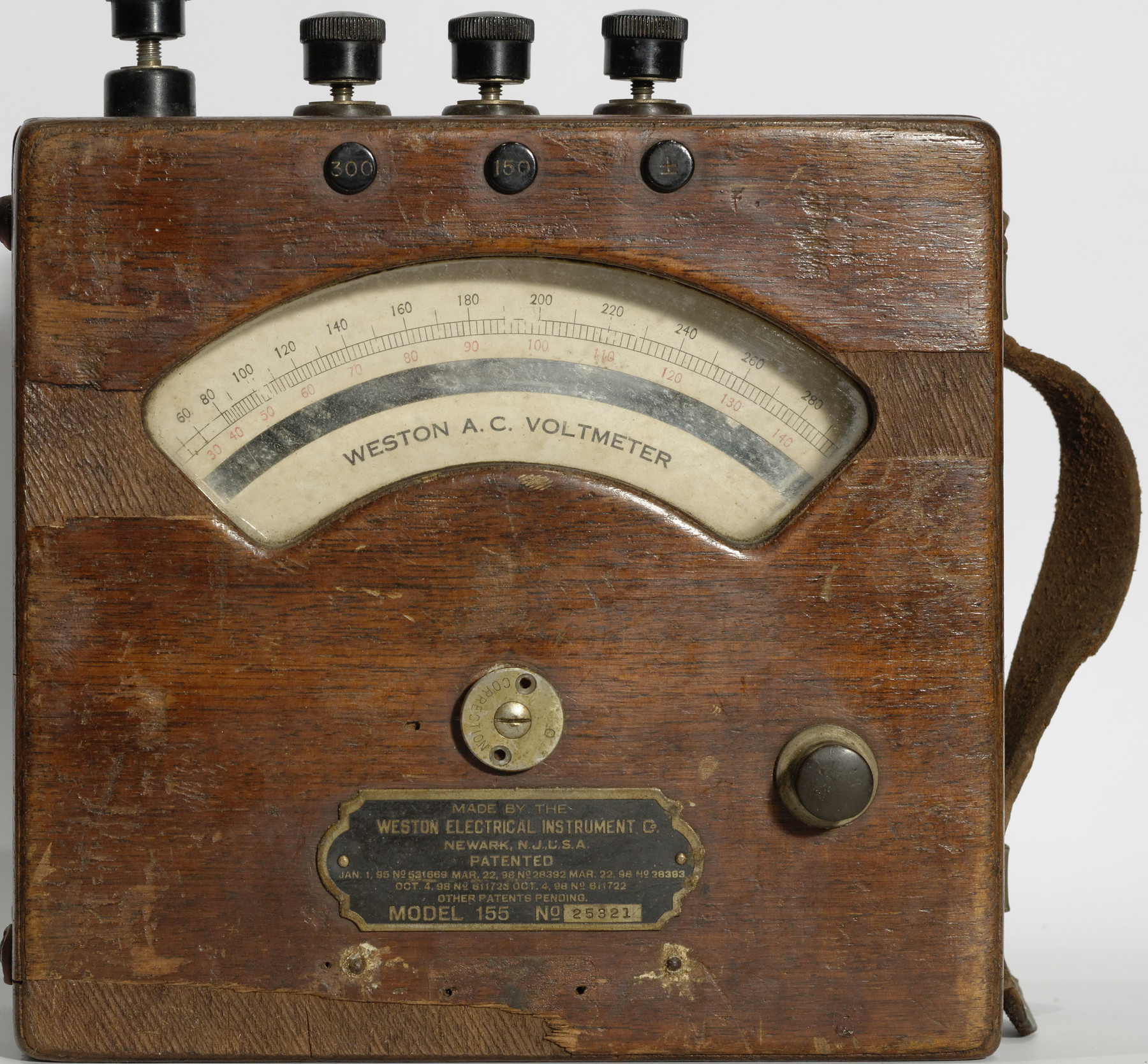
Weston model 155 AC Voltmeter
(click images to enlarge)
Here's the oldest instrument in my collection - a 1920s-era "Model 155" AC voltmeter made by the Weston company founded by Edward Weston no less (the chemist, inventor of the voltage standard cell, not the photographer).
Quite a number of variants of this meter were apparently produced under the "155" designation, both for voltage and current, in various ranges. The one here is a dual range, 150/300 V model, in "heavily used" and modified state.
The original specs on these meters were quite impressive for the 1920s — at the time they were considered laboratory grade and specified at 0.5% accuracy. With their mirrored 150-part scales and balanced, sharp index needles, it was quite possible to take readings to at least 0.5 V resolution on the 150 V scale (would we call that a 2¾ digit instrument today? 9 bits, anyway.)
How is our unit doing? Not so well it turns out, initial check shows no reaction to voltage, an open circuit. Then there's that ominous 4th binding post (leftmost in the photos), of a different type than the others — by comparison with photos found on the web, this looks like an aftermarket modification.
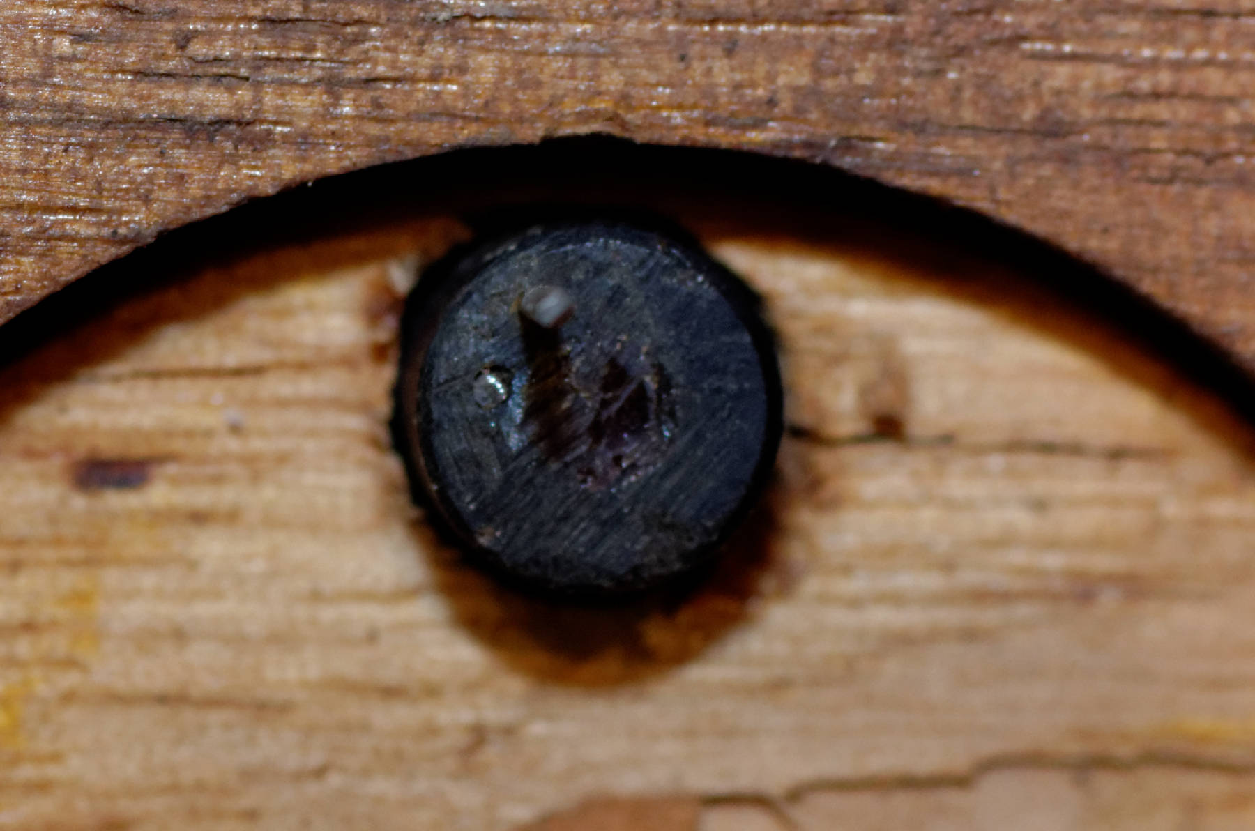
*That's easy to fix however, drill a thin hole into the plastic part (1920s – is that vulcanized rubber?) and stick in a steel pin. If you happen to have a half-broken 0.8 mm drill bit around, just leave it there, it does the trick perfectly in one step :-)
The case has an L-shaped front/bottom part that can slide off after loosening two screws on the bottom. (Be sure to remove the brass insert for the zero-adjust screw first, or the eccentrically placed pin at its inside will break off. (Apparently, this is exactly what happened to one of the previous owners. *)
Inside, we find a very nice meter movement. The brass plate on the cover lists a number of related 1890s patents for the meter and needle.
There's also a pushbutton on the front, inside we find simply two strips of sheet metal pushing against each other. In this unit, there's a shorting wire across that contact ... strange.
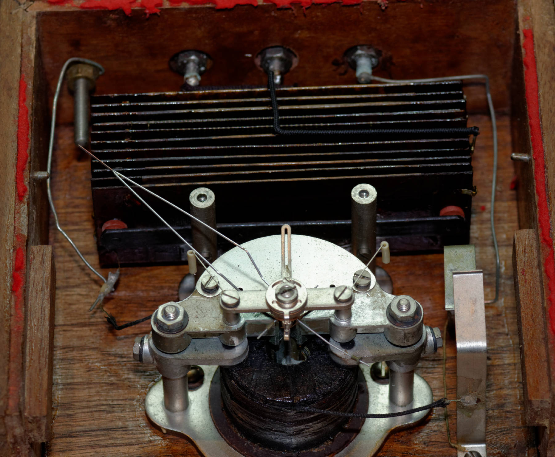
Anyway, it now becomes clear that the extra binding post was added so that the meter's coil can be accessed directly. Nicely enough, the coil seems intact at 128 Ohms. Let's grab the next best 1.8 kΩ resistor, hook it up in series and see if anything is moving! (A variac comes in really handy here and makes this procedure a bit safer too, provided it's of the isolated variety).
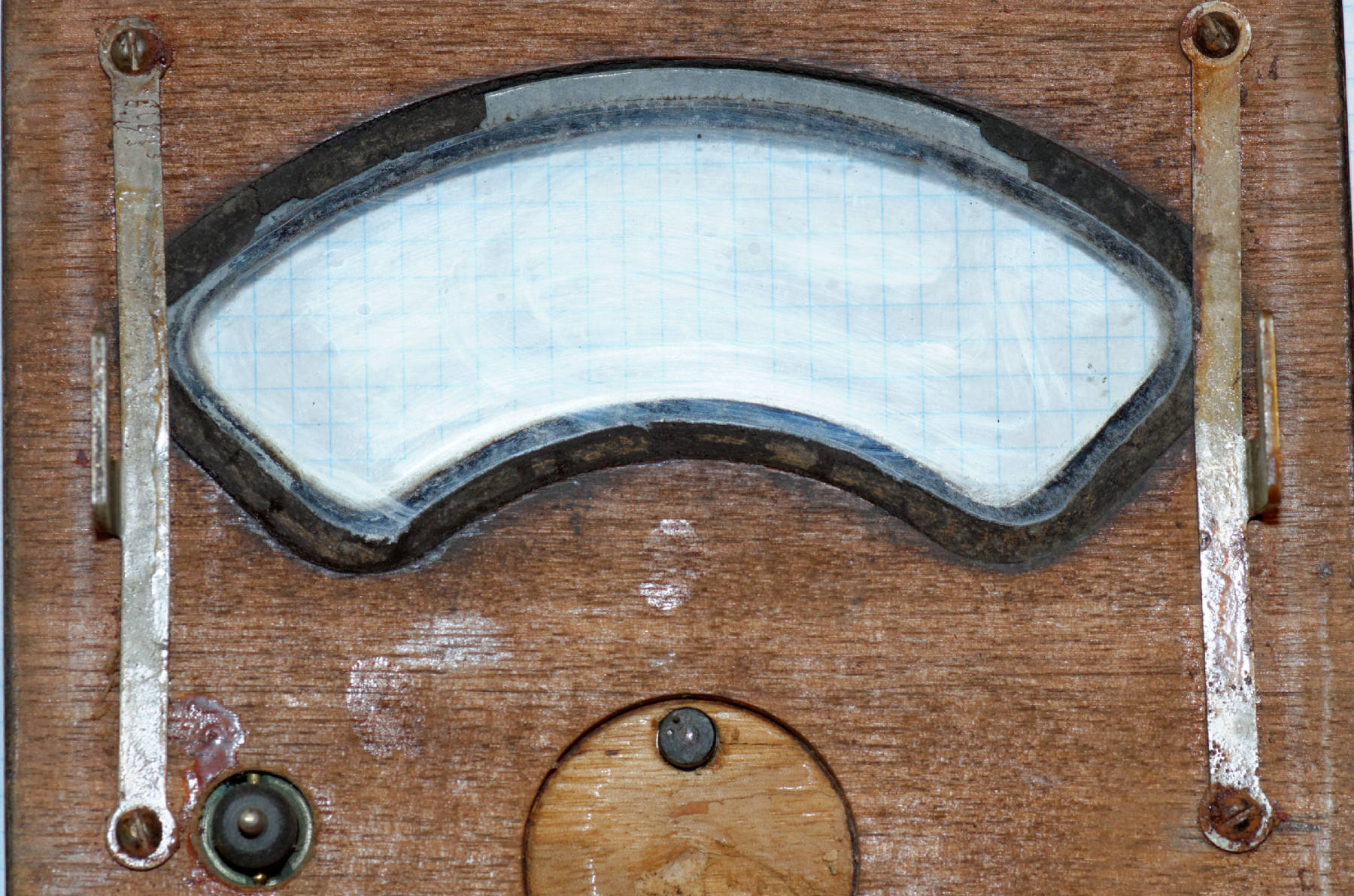
Faceplate seen from inside
For a first test, with 1.8 kΩ in series, we reach full deflection at 109 Volts. The meter is moving and seems smooth, great! Let's see – Rv is exactly 1780 Ohms, Ri is 128 Ω, 109 V / (1780+128) Ω = 53 mA for full deflection. Applying Ohm's law backwards yields a series resistor of 2500 Ω for the intended 150 V scale. What does the old catalog page say?
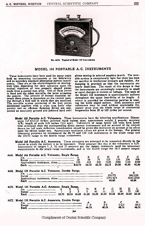
«4688. Model 155 Portable A.C. Voltmeter, Double Range.
No.B: Range 300/150 V. Approximate Resistance 5000/2500 Ohms.»
Spot on! But what's that smell? Ah ... the resistor is a 1 Watt part, but we're running it at 1780 Ω * (53 mA)2 = 5 W. Poor thing.
So let's find something suitable in the high-wattage resistor junkbox. What about 2k2, 9 Watt ceramic? OK, add 270 Ω in series – now we're really close, 150 V reading for 148 V in.
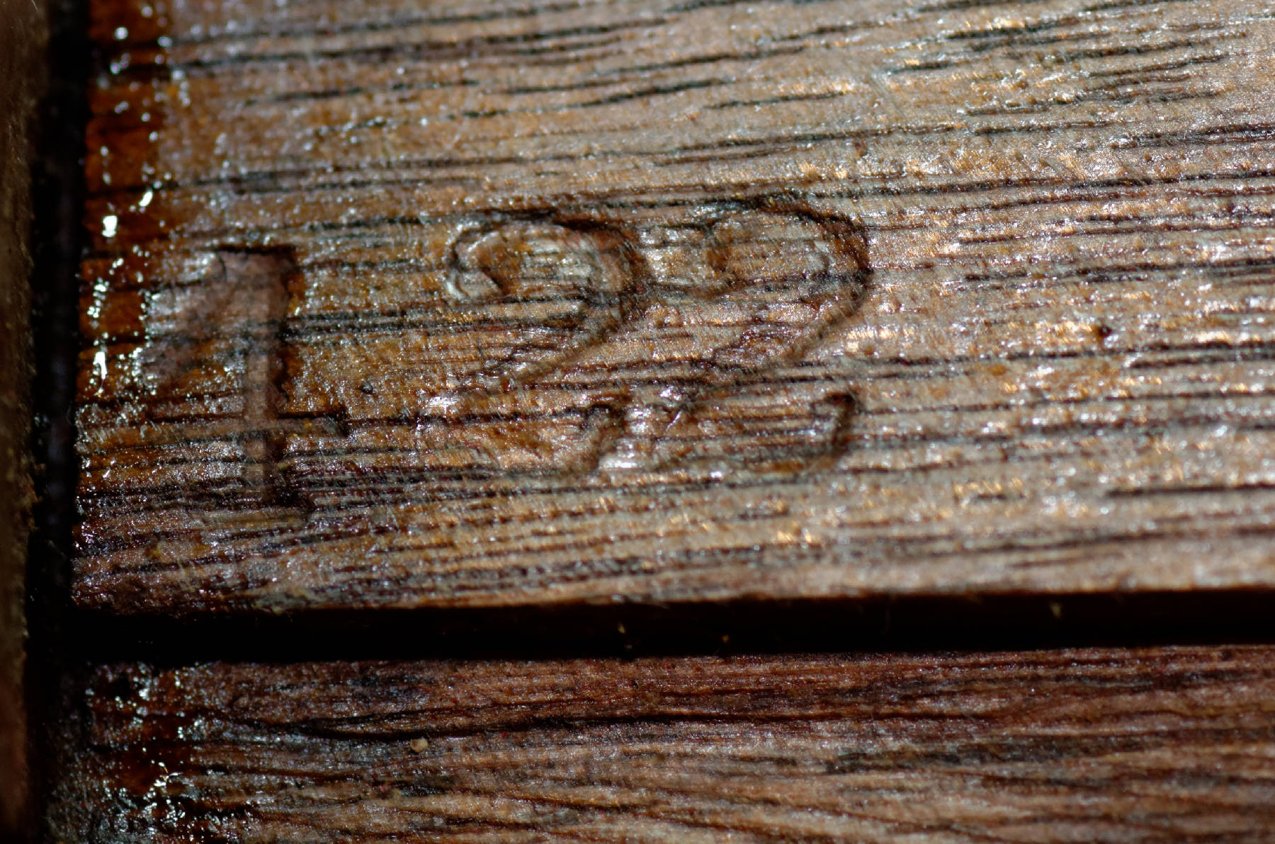
** Case stamped "4 22" — manufactured April 1922?
A quick check tells us that $48 in 1922
would be $666 today.
There's a reason these meters cost $48 in the 1920s ** ... that's not just for the nice meter movement. In order to obtain 0.5% accuracy, the resistor has to be that good too, despite of significant self heating - (300 V)2 / 5000 Ω = 18 Watts at full deflection in the top range, and that's just to read the voltage!
These moving-iron meters are not very sensitive ... even in today's catalogs, the manufacturers still ashamedly mumble somthing about a "burden" of a few watts for the modern panel-mount variety.

That also explains the button: press to measure, but don't measure too long to avoid self-heating. Another apropos – I found pictures on the net of several 600 Volt versions of this meter – they have a larger case with cooling holes drilled in at the top where the resistors are. Apparently, 36 Watts were a bit much to keep inside the little wooden case ...
Let's test our resistors. Not a messy temperature measurement to get the TC, just a cold resistance / hot resistance
comparison after a few minutes at 150 Volts. The resistance goes up from 2.524 kΩ at ambient to
2.491 kΩ after a few minutes, or in other words 1.3% change. So much for the 0.5% lab instrument.
We can also set the input for full reading and see the change — 148 Volt at cold, 149.5 Volt reading; after a
few minutes, 147.5 Volt — the same 1.3%.
Meter gooood, resistor baaaad!
What can be improved? we can use resistors with a lower TC, we can heat them less, we can try to compensate using different materials in series, etc. Without major changes to the case, any new resistor will still dissipate heat into the case, so the amount of self-heating will be hard to reduce much. Lower TC is doable, there are fairly standard high wattage resistors with TC down to 100 ppm/K. Estimating ΔT = (100°C-25°C) = 75 K * 100 ppm/K or 0.75%. Are these old wirewounds really so good or does that 0.5% spec only apply at some low power-on duty? Curious minds want to know ...
Wikipedia: «Manganin is a trademarked name for an alloy of typically 86% copper, 12% manganese, and 2% nickel. It was first developed by Edward Weston in 1892, improving upon his Constantan (1887).» Weston ... ? Weston ... must have heard that name before somewhere ...