Wayne Kerr 4210 Automatic RLC Meter
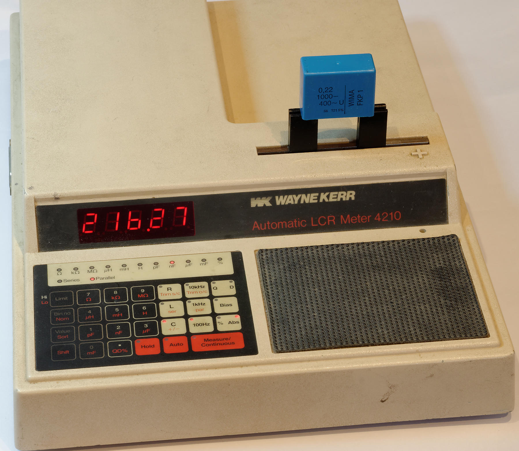
Wayne Kerr 4210 RLC Meter
(click images to enlarge)
Wayne Kerr is a UK manufacturer of test equipment with a 50+ year company history who have long had a strong line of RLC meter products.
The model 4210 was introduced in the mid-1980s. It can measure resistance, inductance or capacitance at
three test frequencies
(100 Hz, 1 kHz or 10 kHz if running from 50 Hz mains,
120 Hz, 1.02 kHz oder 10.2 kHz on a 60 Hz supply).
The meter also displays Q or D factor, or series resistance (ESR) / parallel resistance.
Between 10 Ω–1 MΩ or 100 pF–100 μF, the
instrument's accuracy is 0.1%.
→ Manual
The 4210 comes with a standard IEEE-488 port. Construction is of typical 1980s through-hole variety, the digital part is more or less the standard Intel application circuit for an 8085 CPU supported by a 27128 EPROM, 8155 (256 Byte RAM + I/O), 8279 display/keyboard controller, 2816 EEPROM (for calibration data) and an IEEE-488 controller on a separate but not optional board. (Interestingly, WK used a Motorola family chip, the MC68488, instead of Intel's 8292 — may we assume the latter was not too popular?)
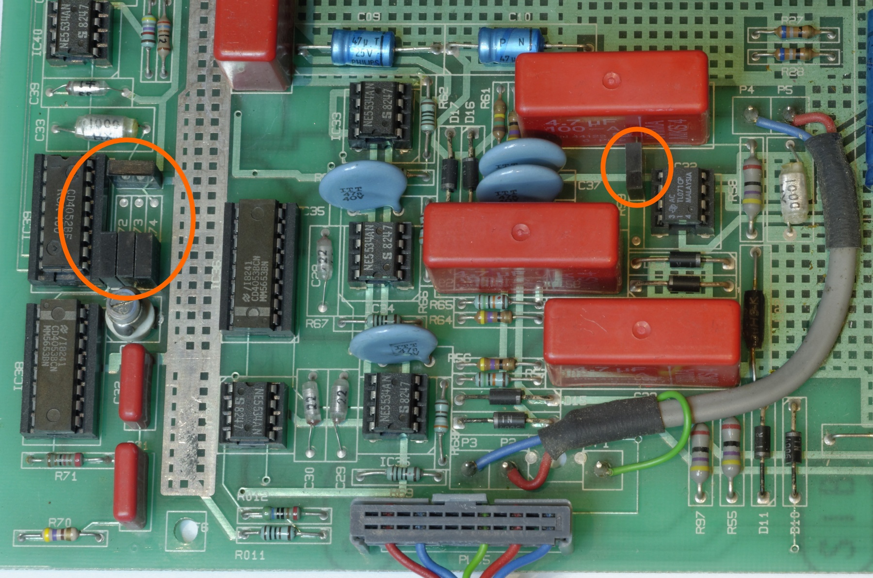
The instrument is built on one main board with cleanly separated analog and digital parts. There are only five precision resistors (0.01%) and just ordinary opamps like NE5534 or TL071, plus some plain 40xx CMOS series analog switches/multiplexers. There are only two hardware trims on the board, a trimpot to set the excitation voltage level, and a trim cap to correct a voltage divider's ratio at 10 kHz. Every other source of error is handled by software calibration.
The instrument's "smarts" are contained in the measurement method and its implementation in software.
The 4210 always measures using four-terminal (Kelvin) sensing. The device under test (DUT) is driven by an AC voltage of 250 mV at one of the three test frequencies. Current through the DUT flows into a current-to-voltage converter (transimpedance amplifier). An analog multiplexer selects either the resulting current-equivalent voltage or one of the voltages from either end of the DUT to feed into a programmable-gain AC amplifier (PGA) and ultimately into a phase-sensitive, integrating A/D converter that is realized using some comparators, analog switches and software.
The instrument's accuracy depends chiefly on the tolerance of the feedback resistor in the I-to-U stage, therefore a 1 kΩ precision component (0.01% tolerance, 10 ppm TC) is used there. Similar resistors are found in the gain control circuit of the PGA (1–1000). Apart from a few more 0.1% resistors, only standard grade components are used — in particular, this design does not need precision capacitors!
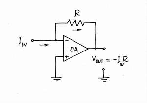
transimpedance amplifier (I to U converter)
Internals
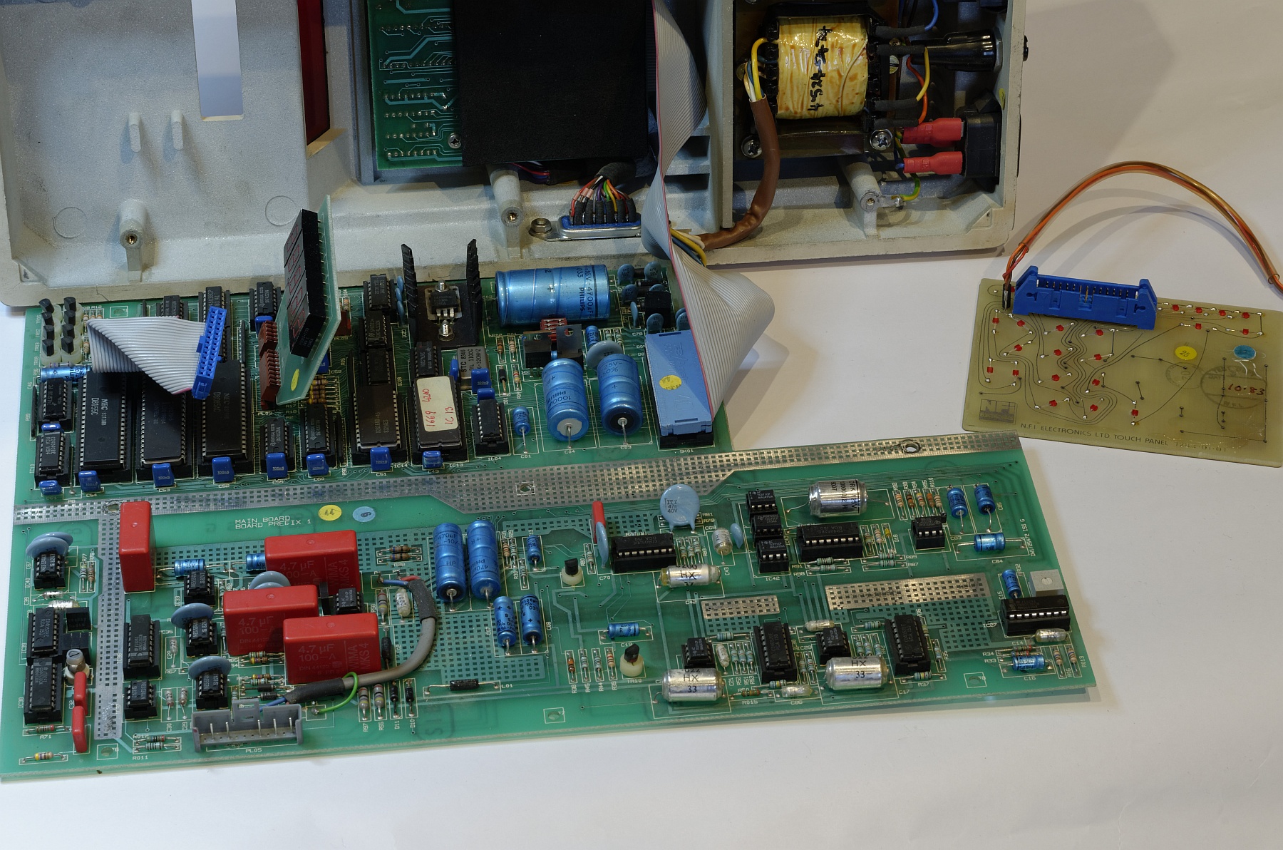
Internals
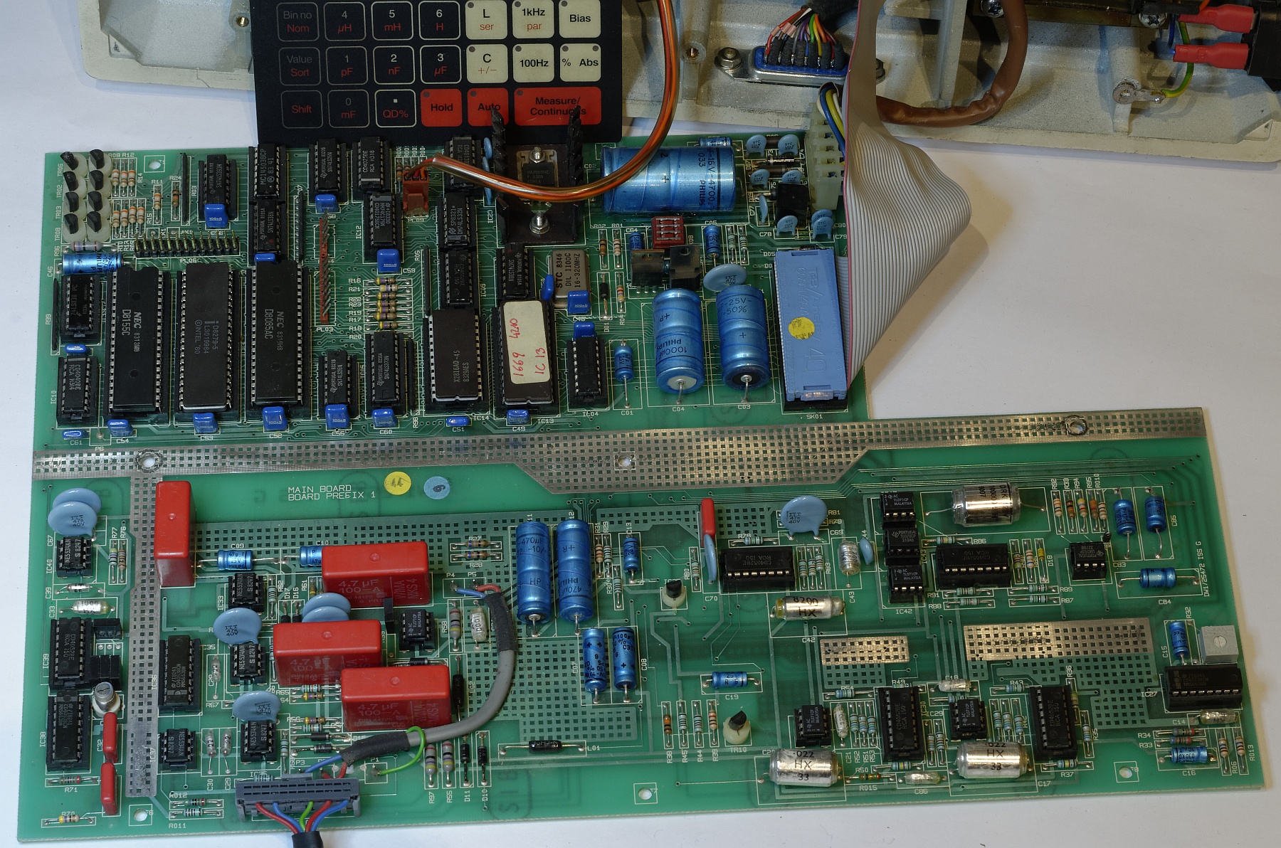
Main Board
Analog Front-End
Only 5 precision resistors (orange circles)
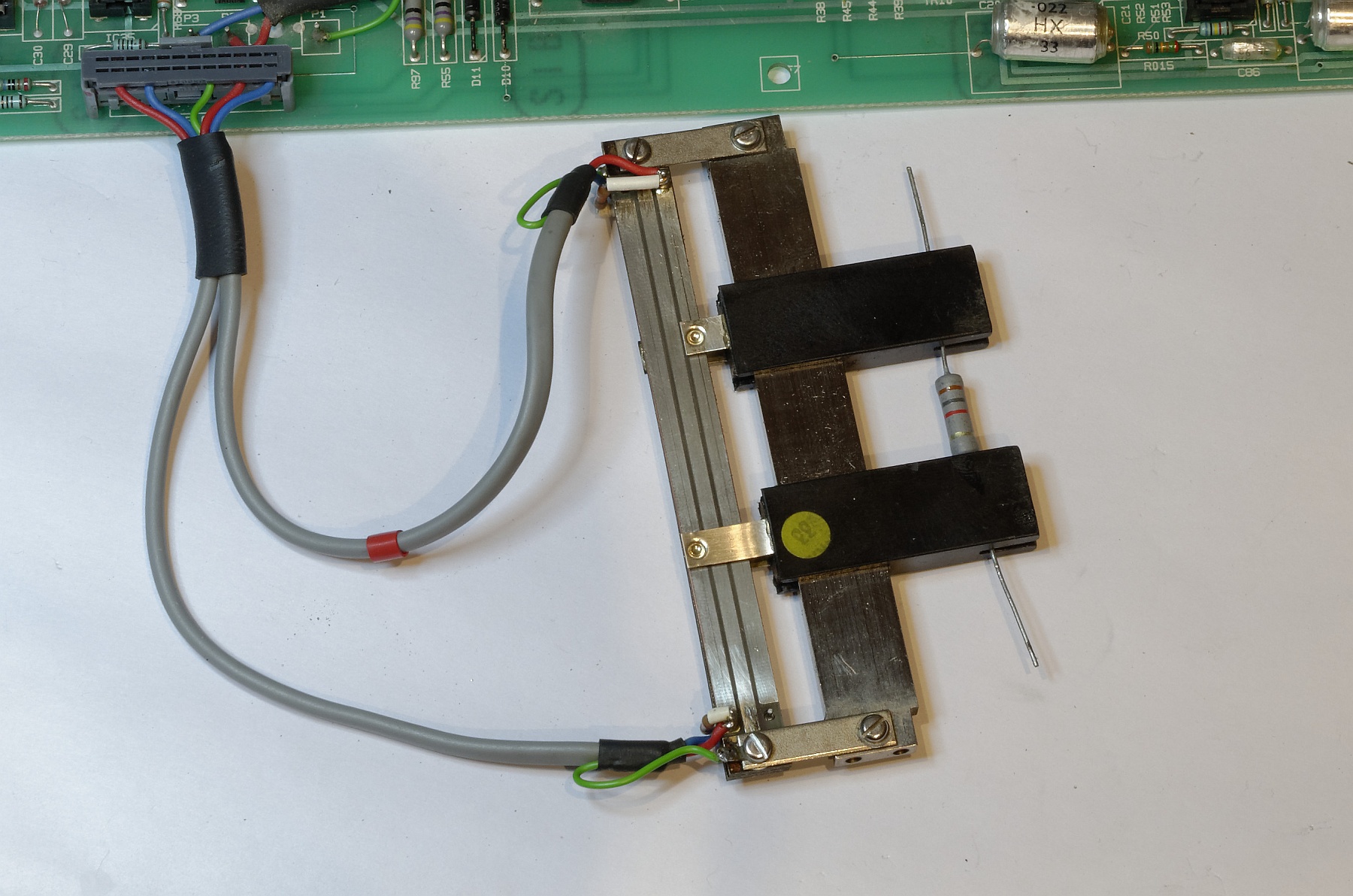
Kelvin Clip Test Fixture