Rohde & Schwarz Tuner ZPV-E1
The ZPV-E1 tuner module accepts signals from 10 Hz(!) to 50 MHz through two BNC inputs with oscilloscope-like impedances of 1 MOhm // 17 pF, allowing oscilloscope probes to be attached. Buttons next to the inputs let the operator indicate that 10:1 divider probes are in use. For low impedance inputs, plug external feed-through terminators of the desired impedance (50 Ω or 75 Ω) into the BNC sockets.
The ZPV-E1 needs a frequency reference signal supplied through a dedicated SYNC input. Sync cannot be derived internally from A or B inputs. The SYNC input has lower sensitivity (10 mV) than the measurement channels, however, this is rarely a problem since the signal is typically supplied by a generator. Only the frequency of the reference signal is important, it is not involved in phase measurements.
Above 25 kHz, the ZPV-E1 locks an internal oscillator to the measurement frequency using a PLL circuit. This oscillator runs at 20 kHz offset to the sync signal and is used to mix the inputs down to the IF. For the 10 Hz-25 kHz range, a PLL would take far too long to lock, but the designers found a clever alternative: A frequency counter inside the tuner measures the Sync frequency, the CPU offsets this value by 20 kHz and generates the oscillator signal through a DDS (direct digital synthesis) circuit built from just a handful of TTL chips. Yes, Herman, there was a DDS before 1980!
Since the ZPV's measurements are always frequency-selective, the E1 tuner with a suitable generator on the Sync input can also be used to measure harmonics (distortion) and spurious frequencies, albeit with the limitation that the mirror frequency (input + 40 kHz) is not suppressed, i.e. this capability can really only be used in the low frequency range. In that range, the DDS frequency can also be set via HPIB control, eliminating the need for an external generator.
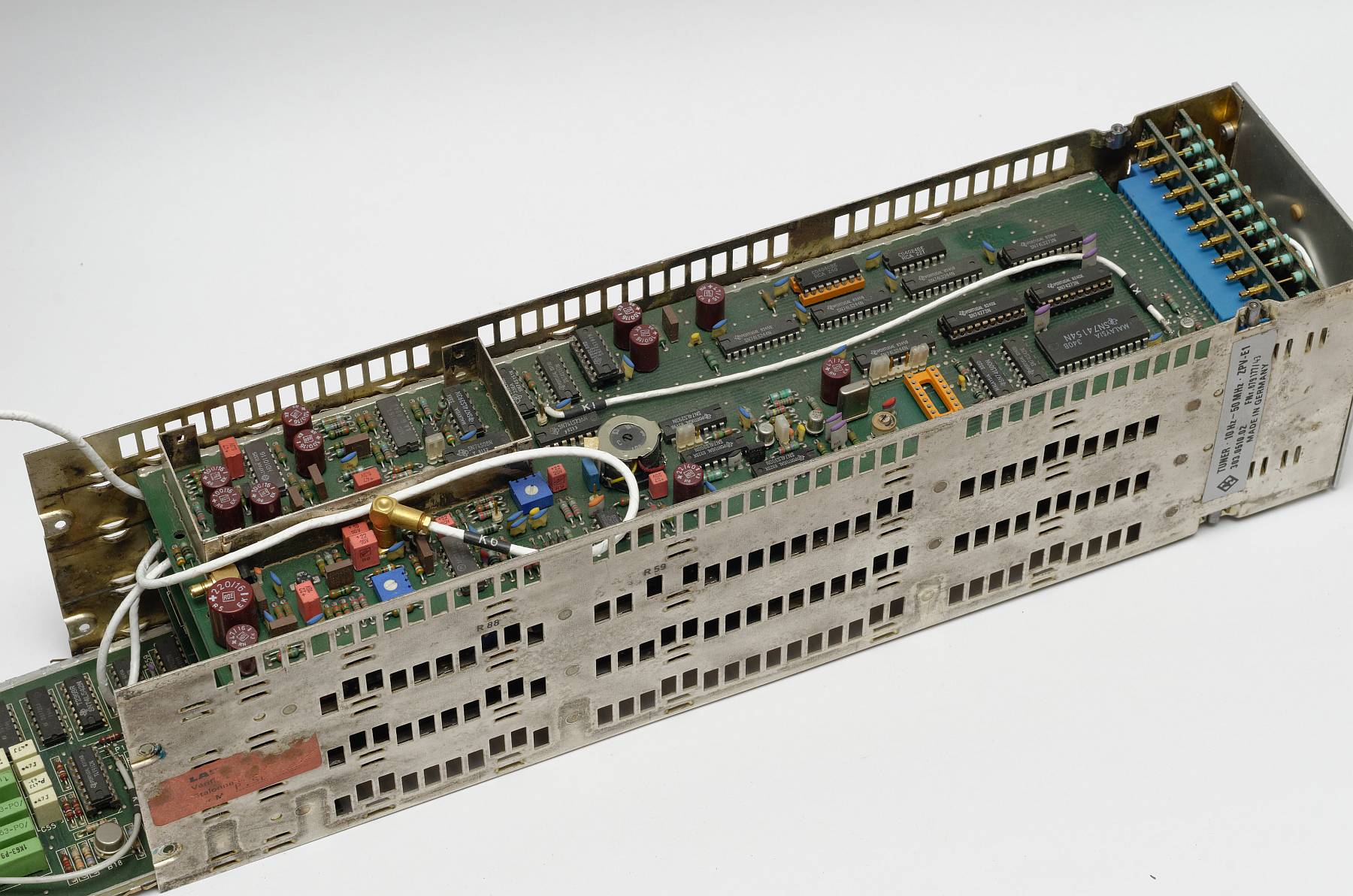
The E1 tuner (10 Hz–50 MHz) inside.
Top board is the frequency counter.
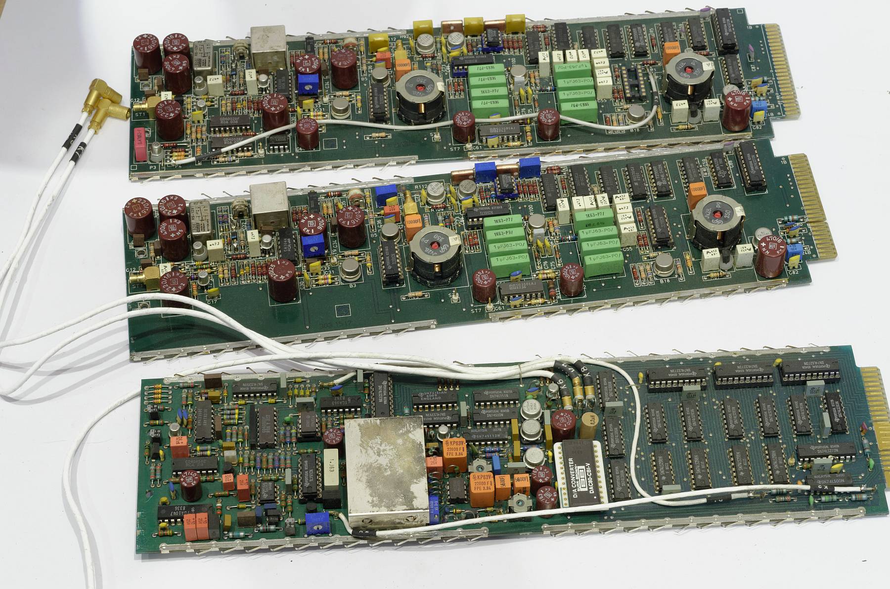
The other boards in the E1 tuner.
Top two are input channels, bottom is the oscillator.
(click images to enlarge)