Rohde & Schwarz Tuners ZPV-E2 and ZPV-E3
The ZPV-E1 tuner module accepts signals from 100 kHz to 1 GHz through two medium-impedance probes that are permanently attached to the unit — much to the aftermarket buyer's pleasure, they can't be lost. Alas, the same cannot be said of the adapters needed to to mate the probes' coaxial-style tips with BNC, N or other connector types. Those are just of a mechanical nature however, so workarounds are not too hard to find.
This tuner works by sub-sampling the input signal, i.e. mixing it with a frequency comb. The core of the circuit is actually hidden in the probe tips, it is a traditional diode-bridge sampling circuit, constructed on a ceramic substrate. The diode bridge is controlled by very short (sub-nanosecond) pulses generated by a transistor in avalanche breakdown mode, triggered from a VCO. This finally explains why the ZPV base unit supplies +120 V to the tuner!
The RF signal is only present at the bridge input. After sampling, only an audio-range IF signal needs to be amplified and processed. The VCO frequency is regulated so that a 20 kHz IF signal is maintained. Because of the sampling principle, any multiple of the VCO frequency offset by 20 kHz could be the actual signal frequency, it does not matter which.
The service manual is a little vague on many of the details. It does explain that the VCO is composed of two separate oscillators, one varactor-tuned L/C circuit in use for input frequencies above 60 MHz, and another one based on a current-controlled monoflop, for the lower frequency ranges.
I therfore undertook some measurements of VCO frequency at different inputs and found that the low-range VCO runs from 0.12 to about 2.75 MHz, whereas the L/C oscillator keeps to a small range around 2.4 MHz. Because of the sampling principle, multiple VCO frequencies will result in the desired 20 kHz IF output for a particular input, as can be seen in the example of an 11 MHz signal, matched by either 1.836667 MHz ×6 or 2.755000 MHz ×4.
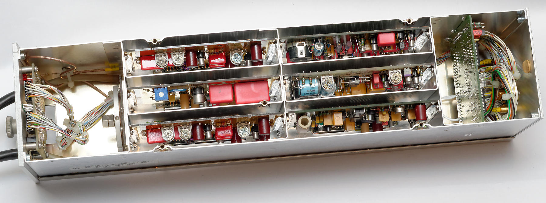
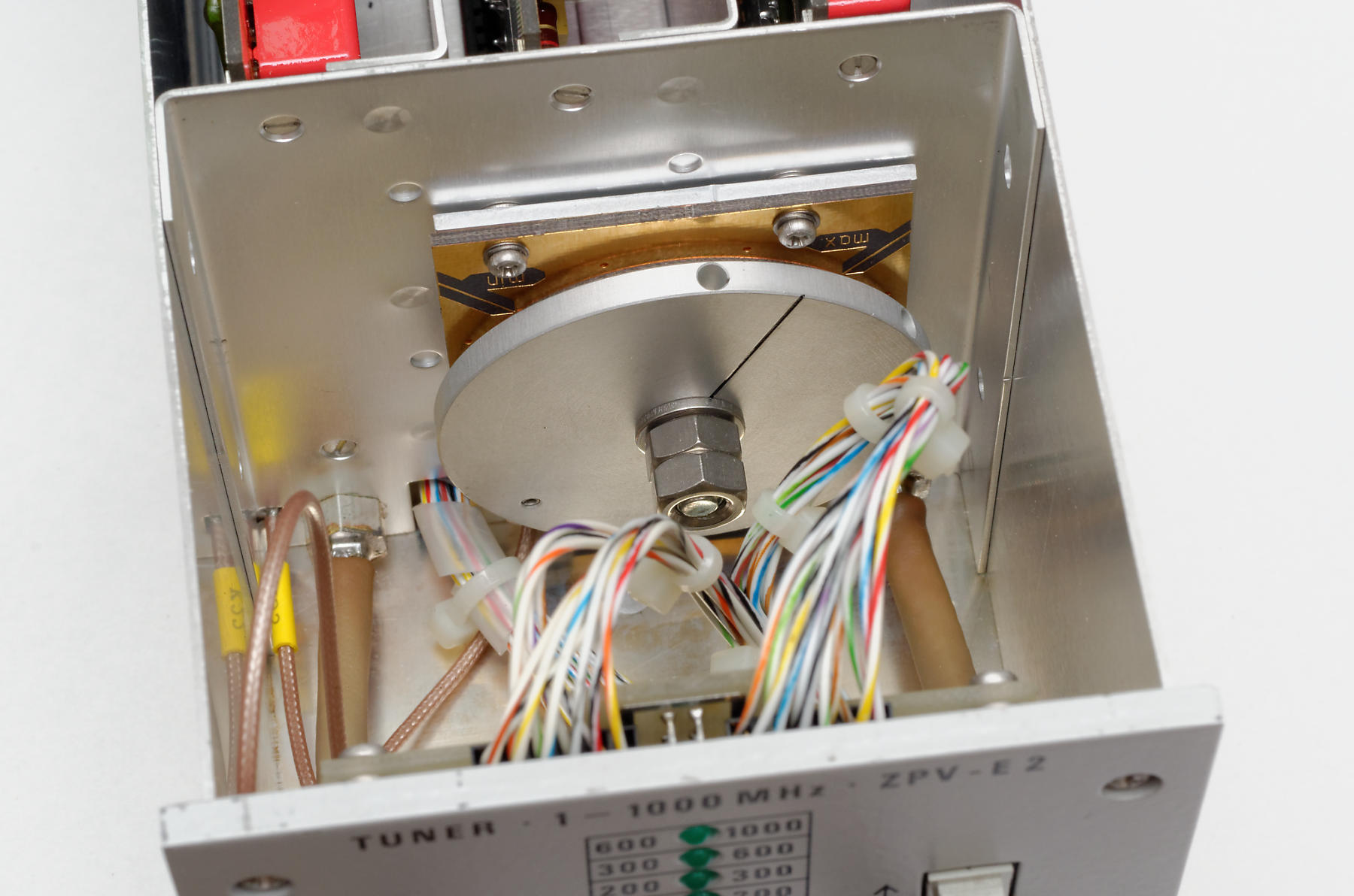
The ZPV-E2 tuner (100 kHz–1 GHz) inside.
(click images to enlarge)
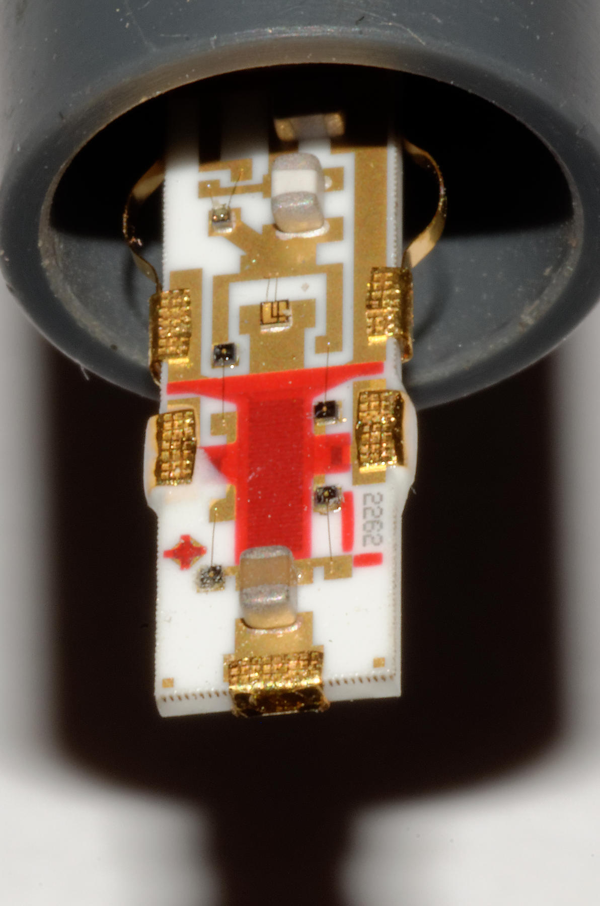
Sampling circuit inside the probe tip
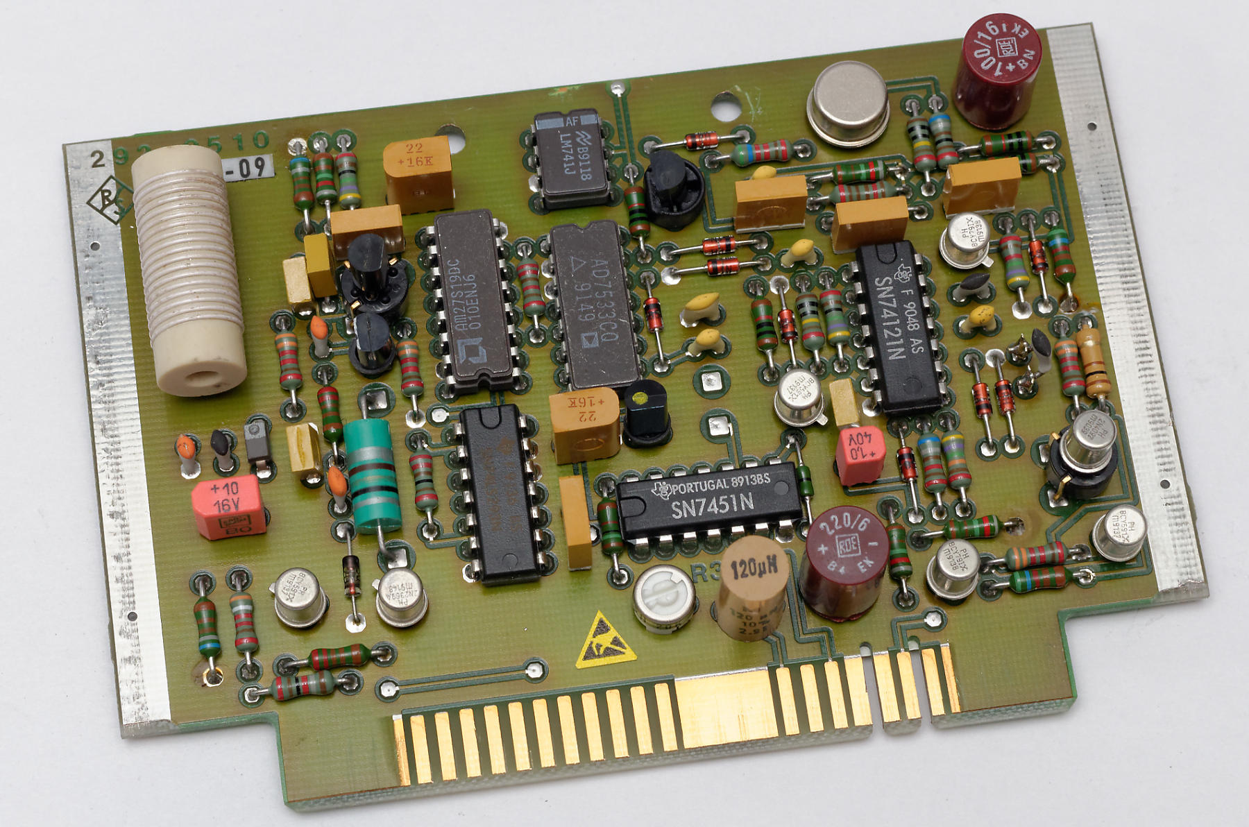
The VCO board
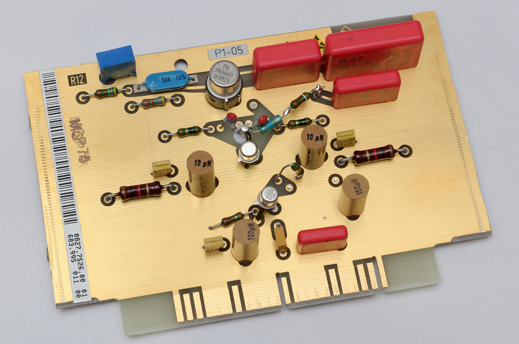
The avalanche pulser board
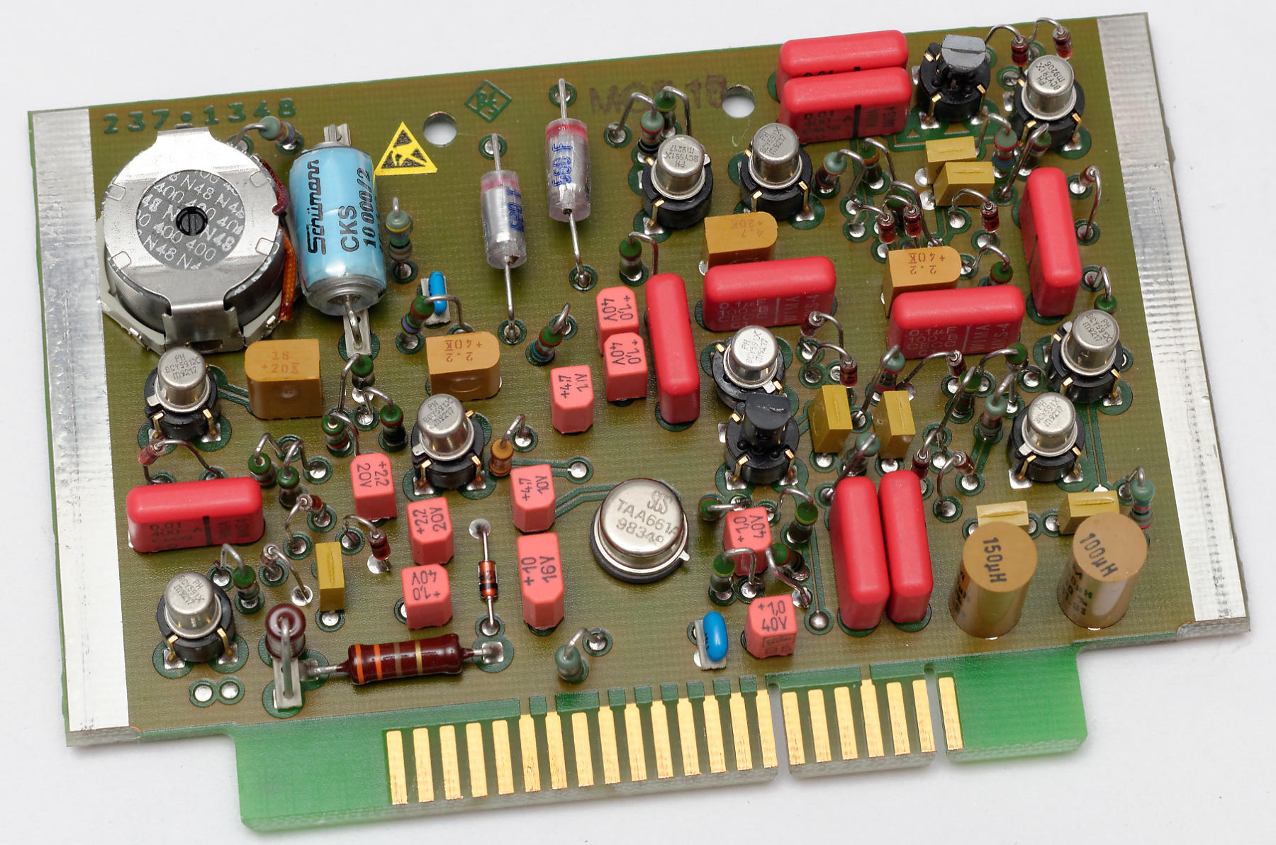
The synchronizer board
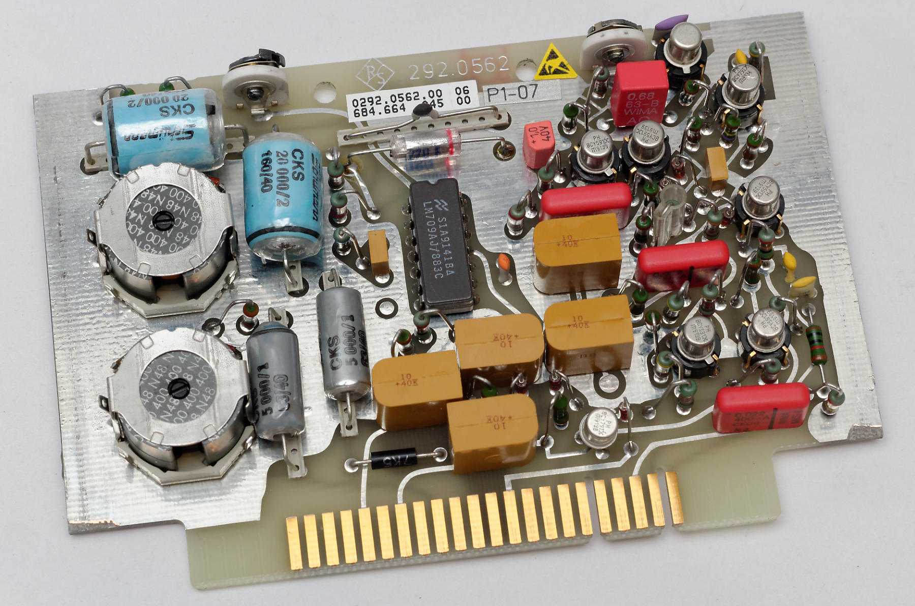
Control amplifier
Post amplifier (one per channel). Note SMD capacitors (1980!)
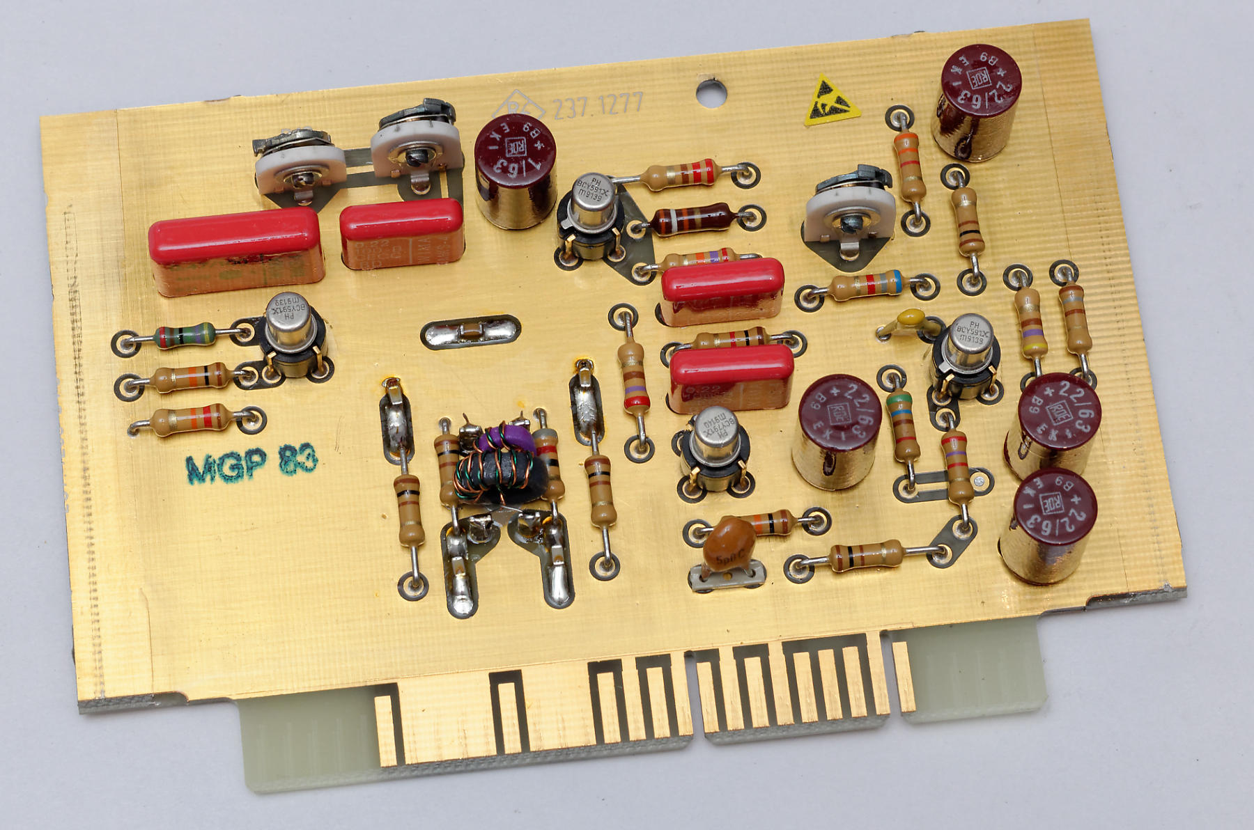
Phase shifter
Tuner ZPV-Z3
The ZPV-E3 is very similar, except that the inputs are N sockets terminated in 50 Ω, with the sampling circuits attached directly behind the input sockets. Eliminating the probe lead capacity allows shorter sampling pulses to reach the diode bridges, increasing the frequency range to 2 GHz (from 300 kHz).
Ancestry
The ZPV-E2 gives the impression that it was more than just a little inspired by the HP 8405A Vector Voltmeter, from the circuit, design and attachment of the probes right down to the choice of 20 kHz IF. There are big differences of course – the 8405A, introduced in 1966, is a purely analog machine and contains not so much as a single integrated circuit. The 8405A's sampling heads are built using conventional leaded components, the sampling pulse generator uses a Step Recovery Diode, the VCO runs at 1–2 MHz only so the input range starts at 1 MHz, IF filters are L/C bandpasses 1 kHz wide, and the frequency range must be selected manually.
However, HP is a little more forthcoming when it comes to specifications, in particular