Improving the Display Backlight on Solartron 7150 / 7150+ Multimeters
Original display backlight
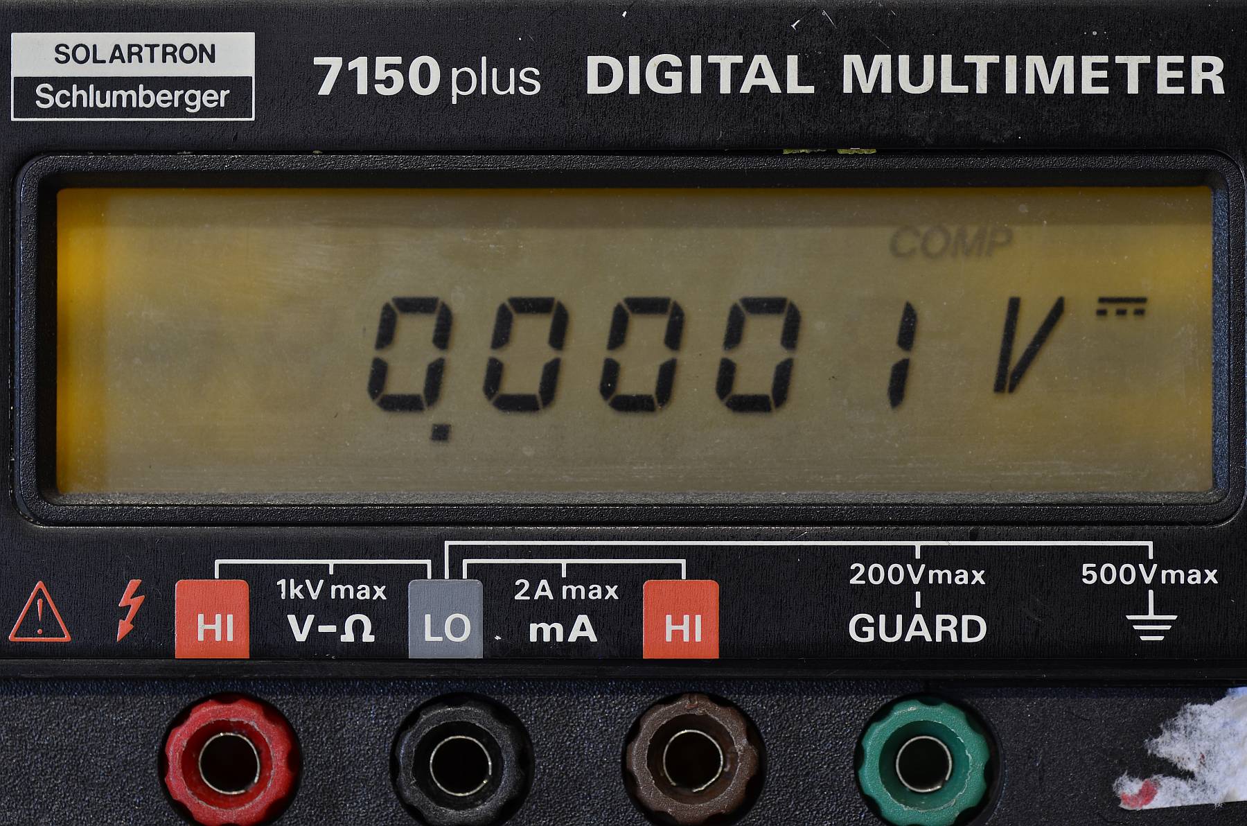
The Solartron/Schlumberger 7150 and 7150plus multimeters have fairly clear liquid crystal displays that only suffer from poor backlight. These old yellow LEDs were not very bright even when they were new ...
The good news is they can easily be replaced with modern superbright white LEDs!
(Click images to enlarge)
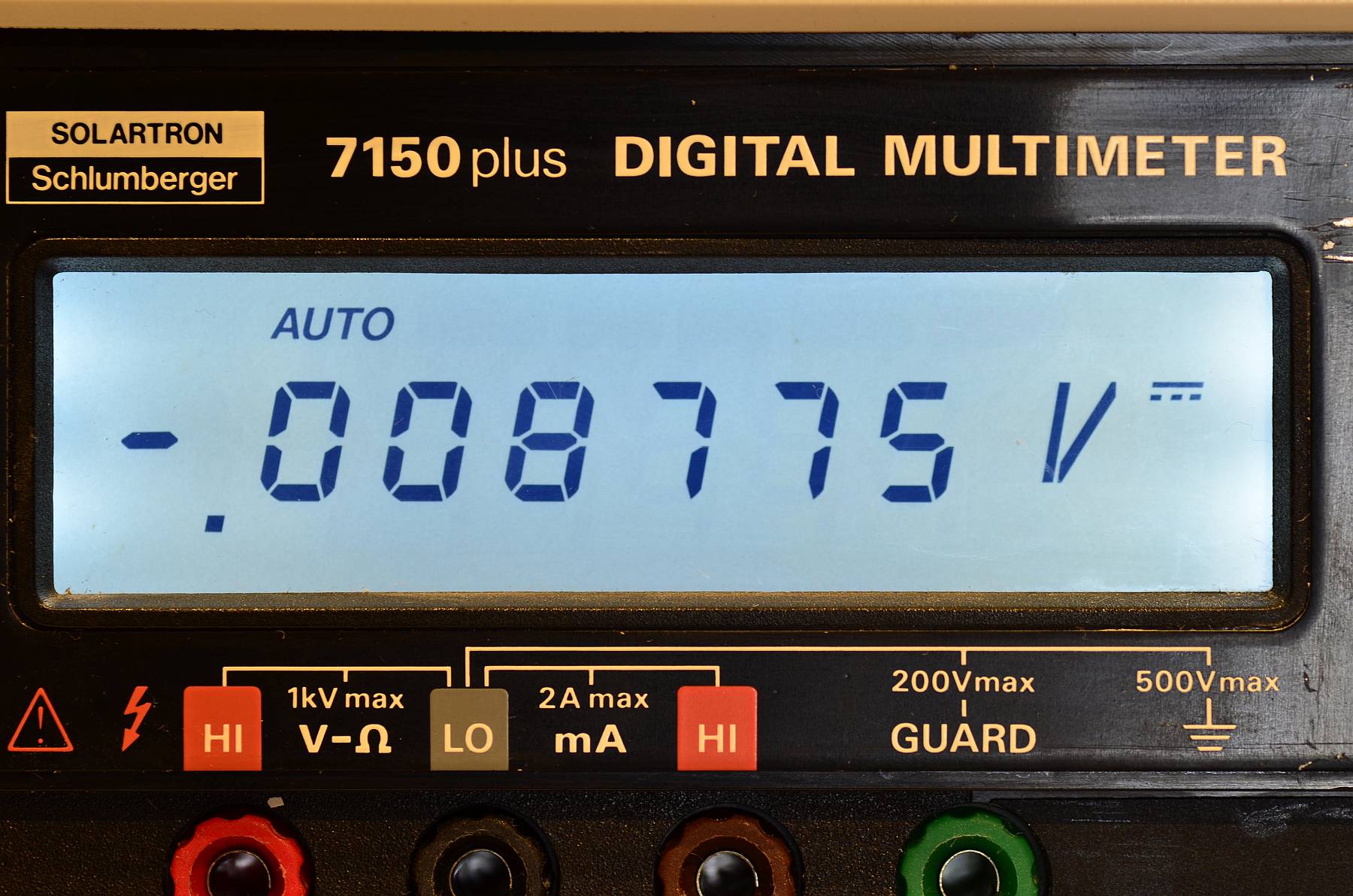
... and after the conversion
CAUTION: These instructions are for experts ONLY. The instrument is operated on mains voltage, which can kill if handled improperly. Incorrect wiring may also create a fire hazard! It is of course self-evident that mains voltage and all inputs must be disconnected completely before working on the instrument!
Preparation: Open the enclosure, flip the analog (top) circuit board upward, remove the two screws holding the mains transformer, then take the digital (bottom) circuit board out of the lower half of the enclosure together with the display board and back panel. Disconnect the power cable from the analog board, the ground connector from the shield between the boards, and the two interconnecting cables from the digital board. Unplug the display board from the digital board and separate the digital board, then remove the retainer screw on the side and unplug the display board from the digital board. (It remains connected to the analog board.)
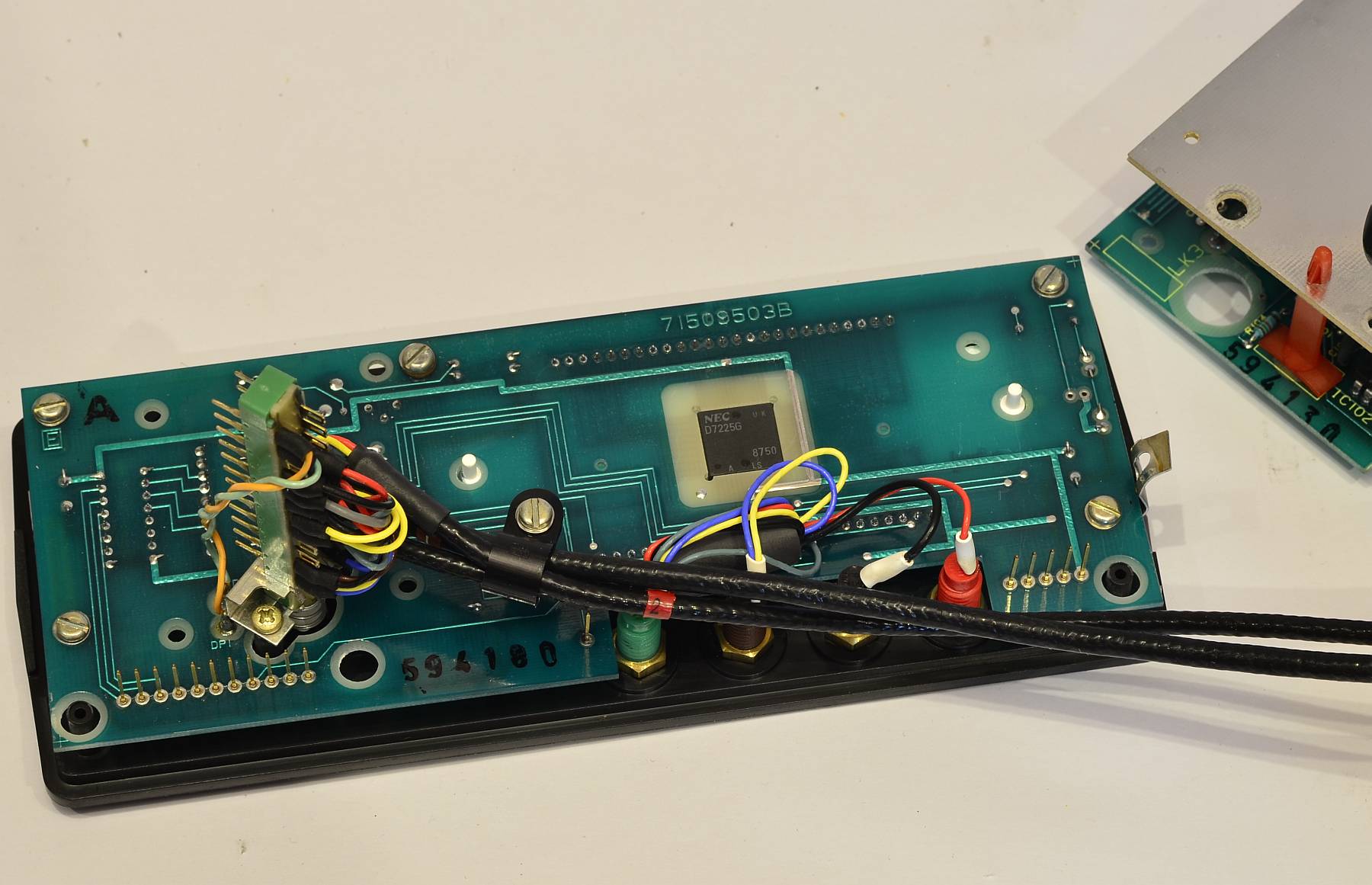
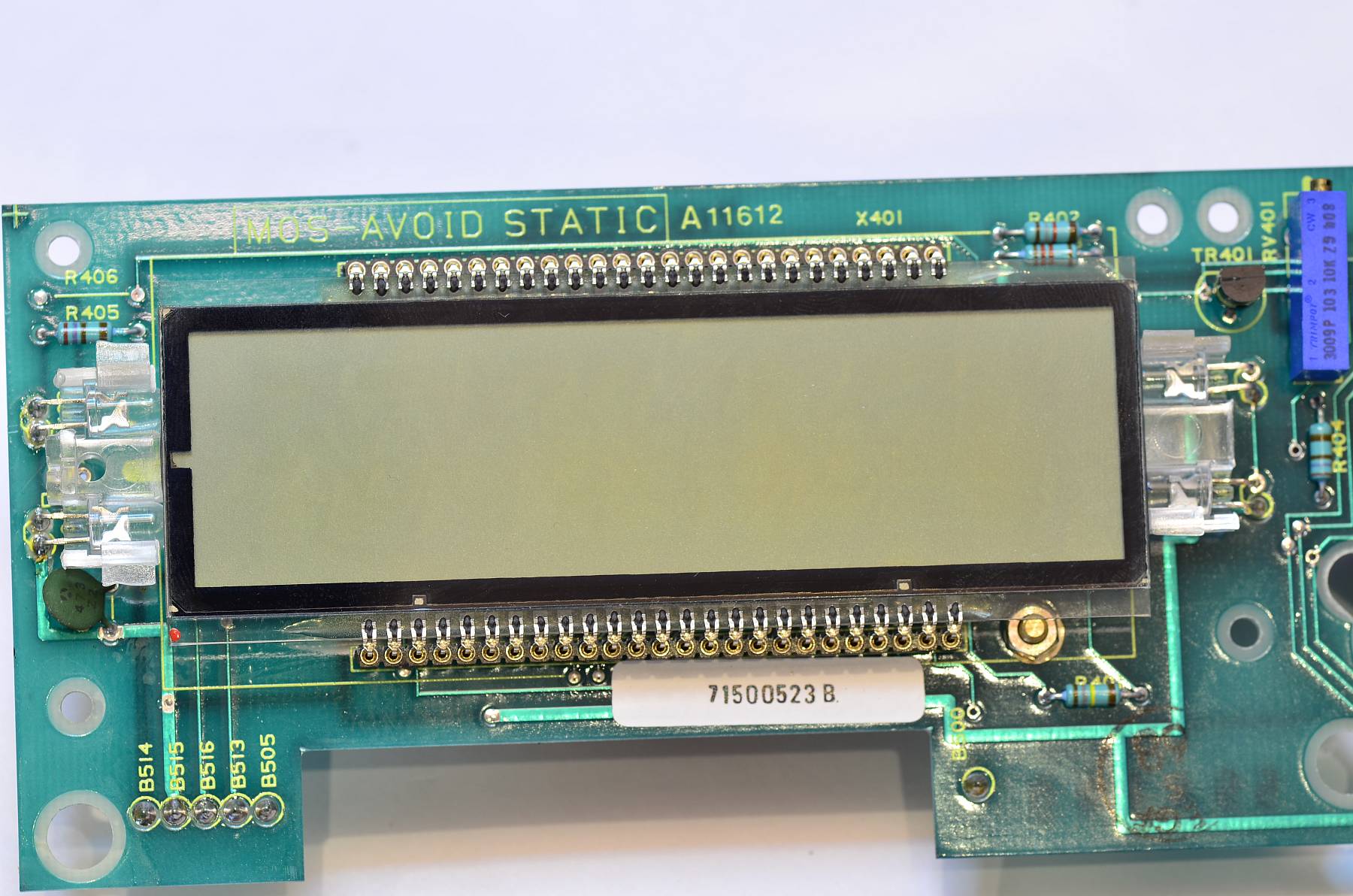
Display board, back side. At the posts on the board, de-solder the two wires coming from the pushbutton switch. Remove the screws holding the PCB to the front panel.
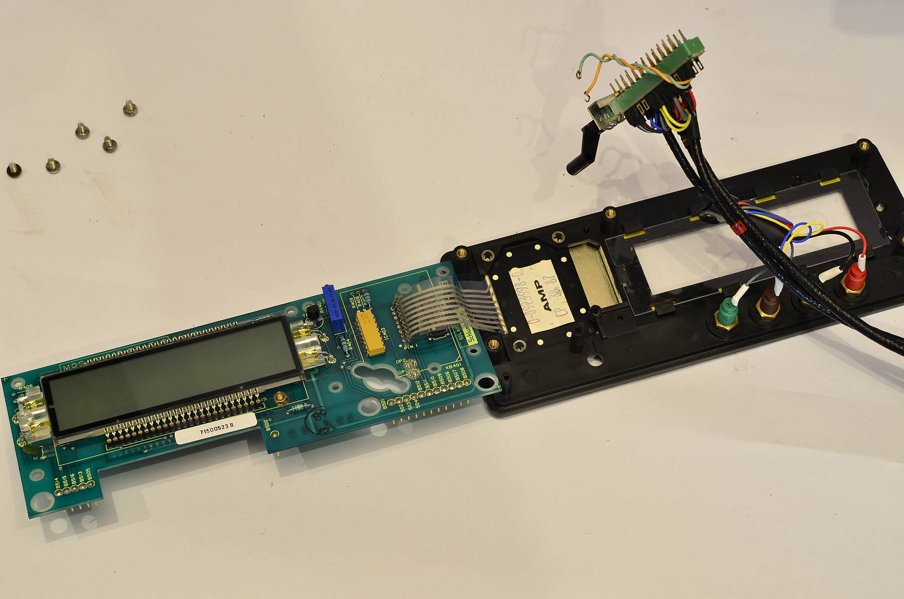
Carefully unfold the assembly. The Flex-strip is rather robust as they come, but it sure is better to be safe than sorry!
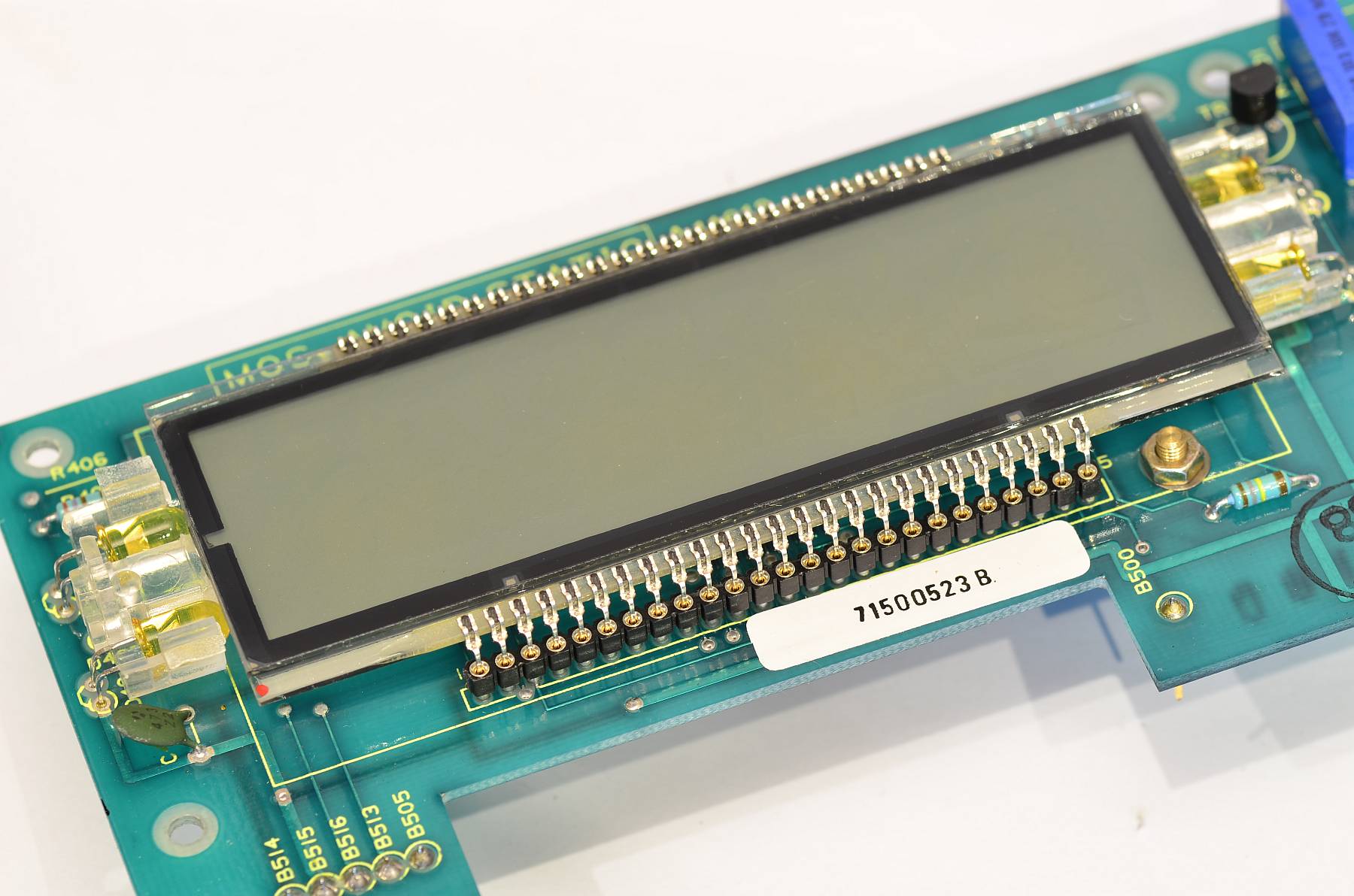
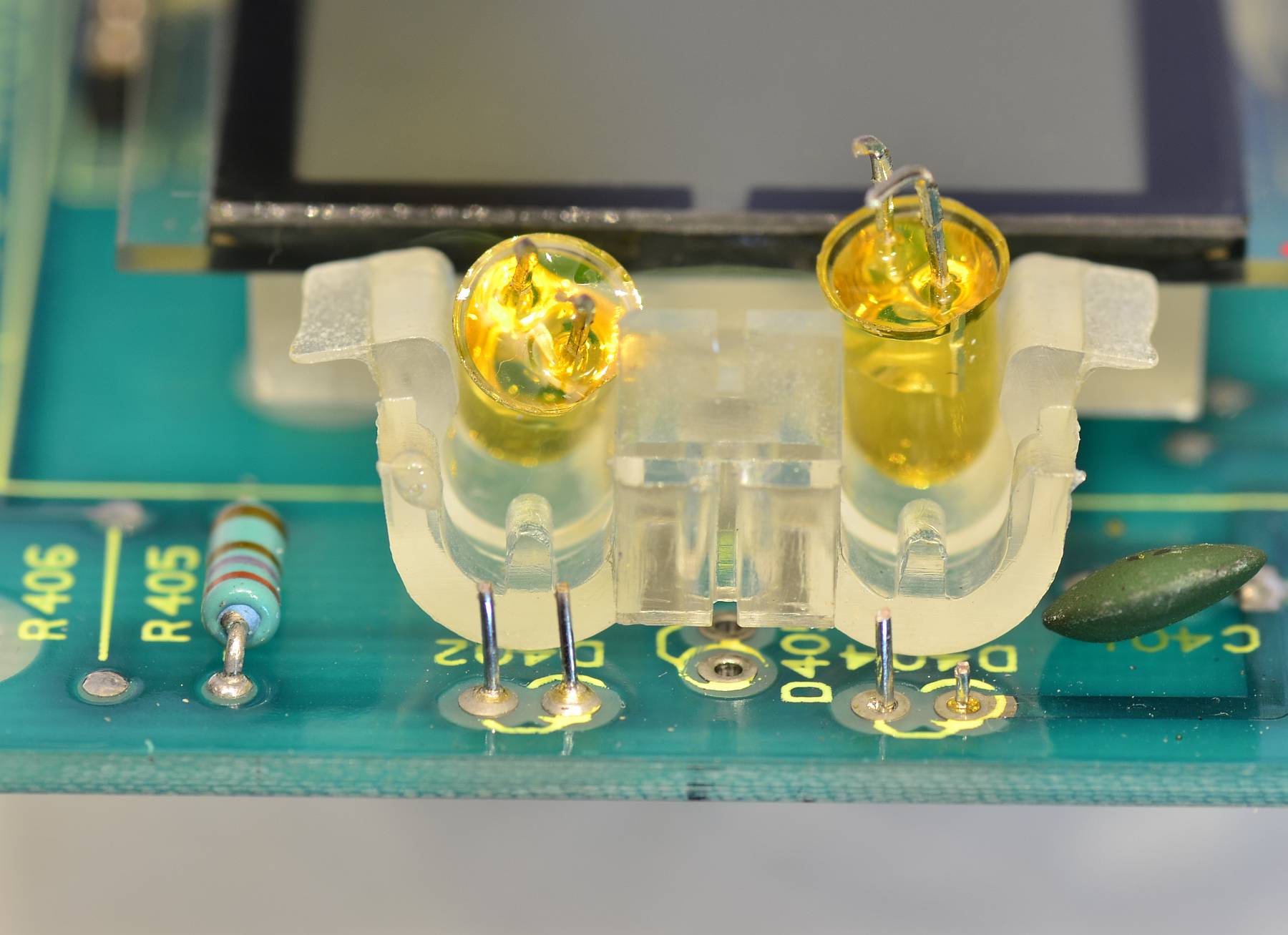
The four yellow LEDs on the sides of the display will be replaced by bright white 5mm LEDs.
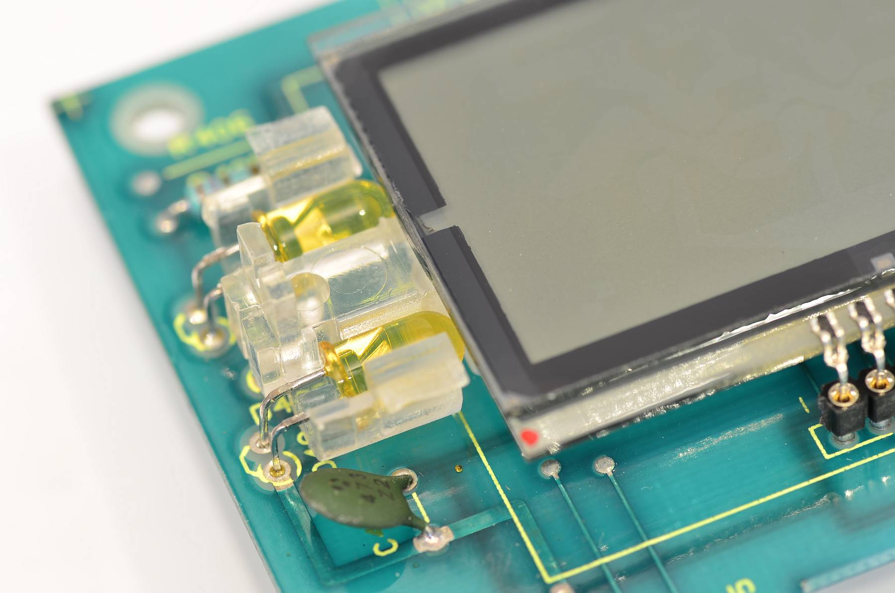
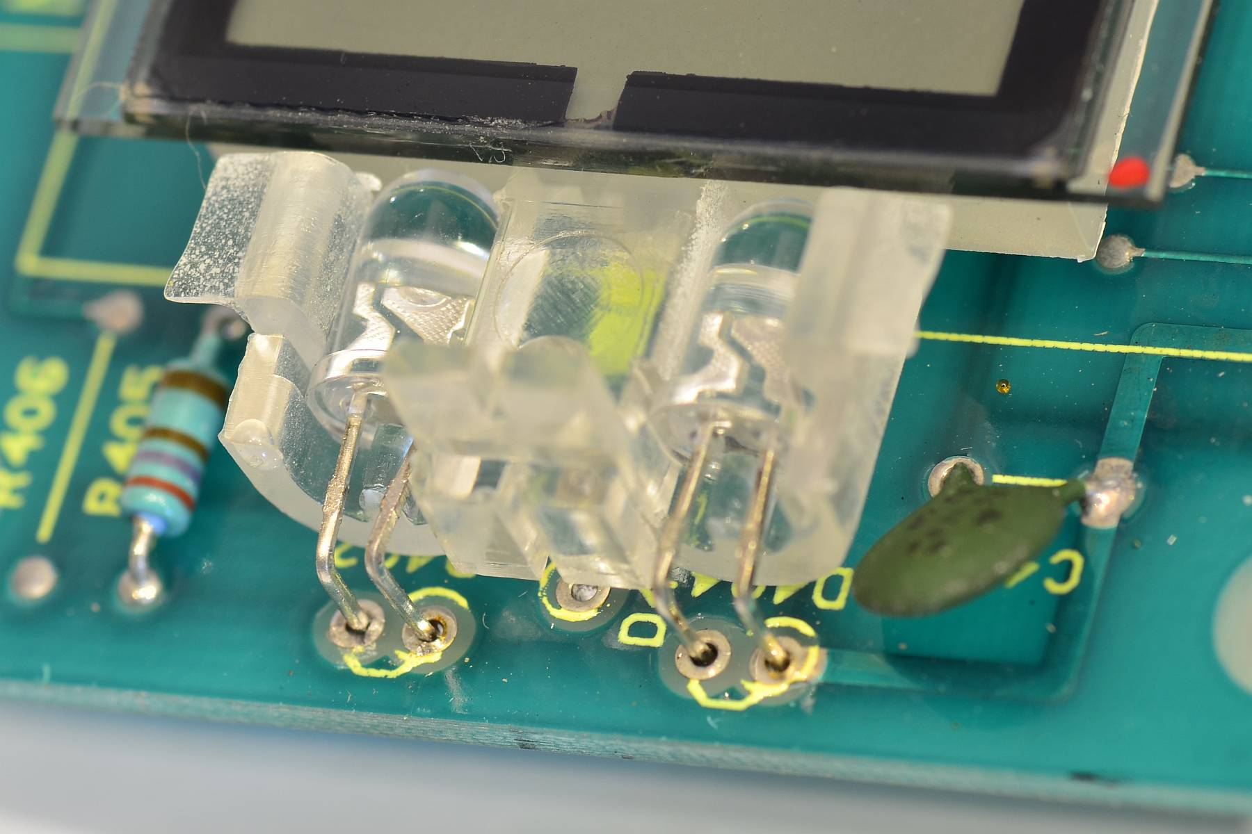
Detail. The cathode pins are oriented toward the bottom (toward the green capacitor).
Just cut the old LEDs off above the board and de-solder the leftover parts of the pins. Pry the LEDs out bottom first.
The new LEDs are more easy to insert if you angle and pre-cut the leads. You will still need some gentle force to push them in all the way. The LEDs have to touch the light distributor plastic strip for uniform backlight!
Four new LEDs are in place and soldered down!
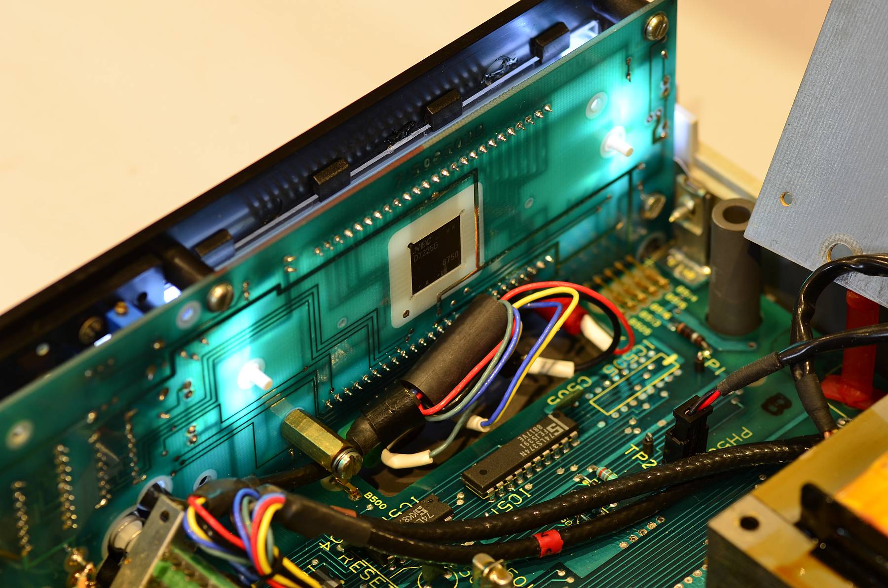
Partially re-assembled for function check
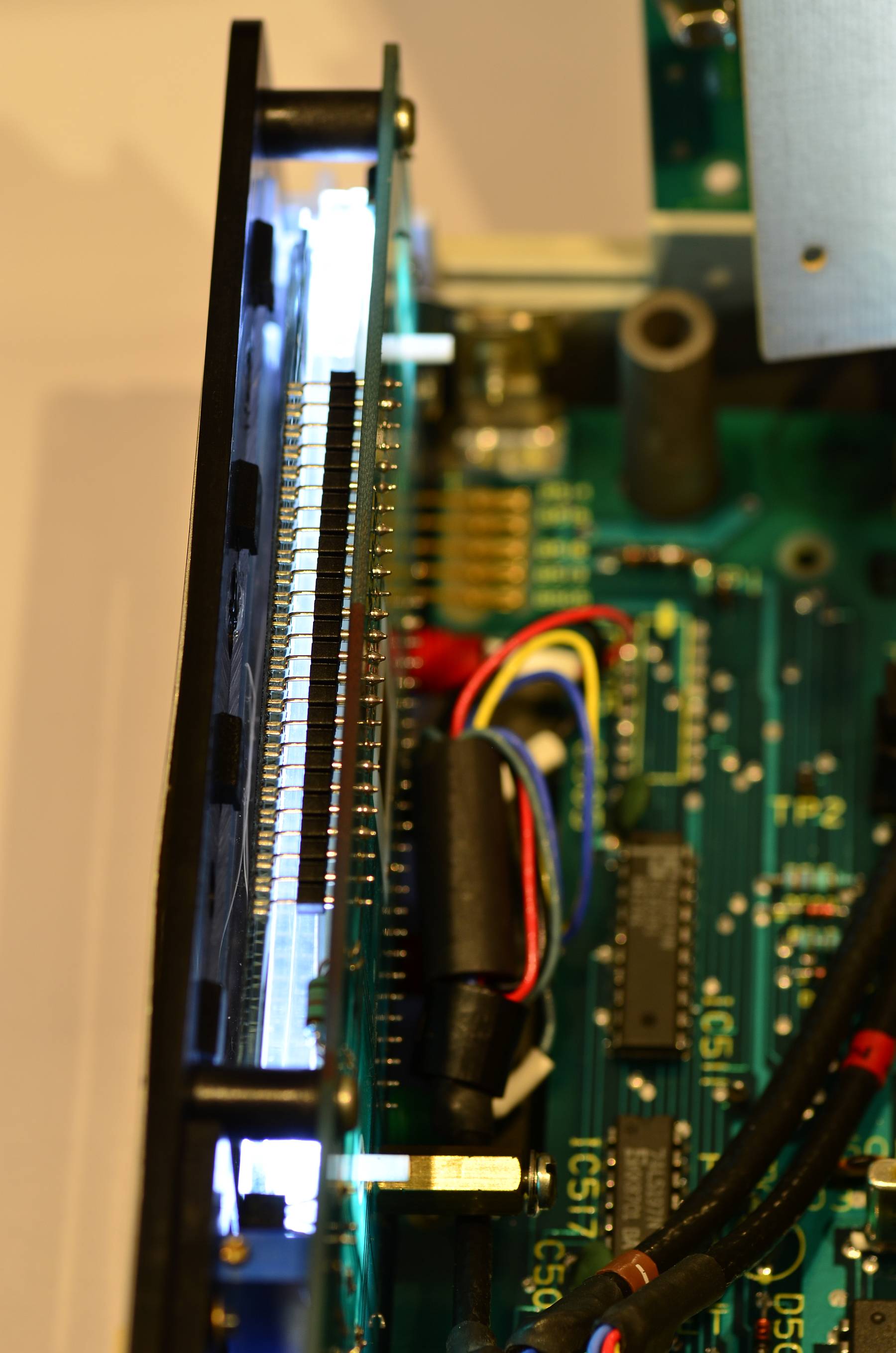
Display seen from above
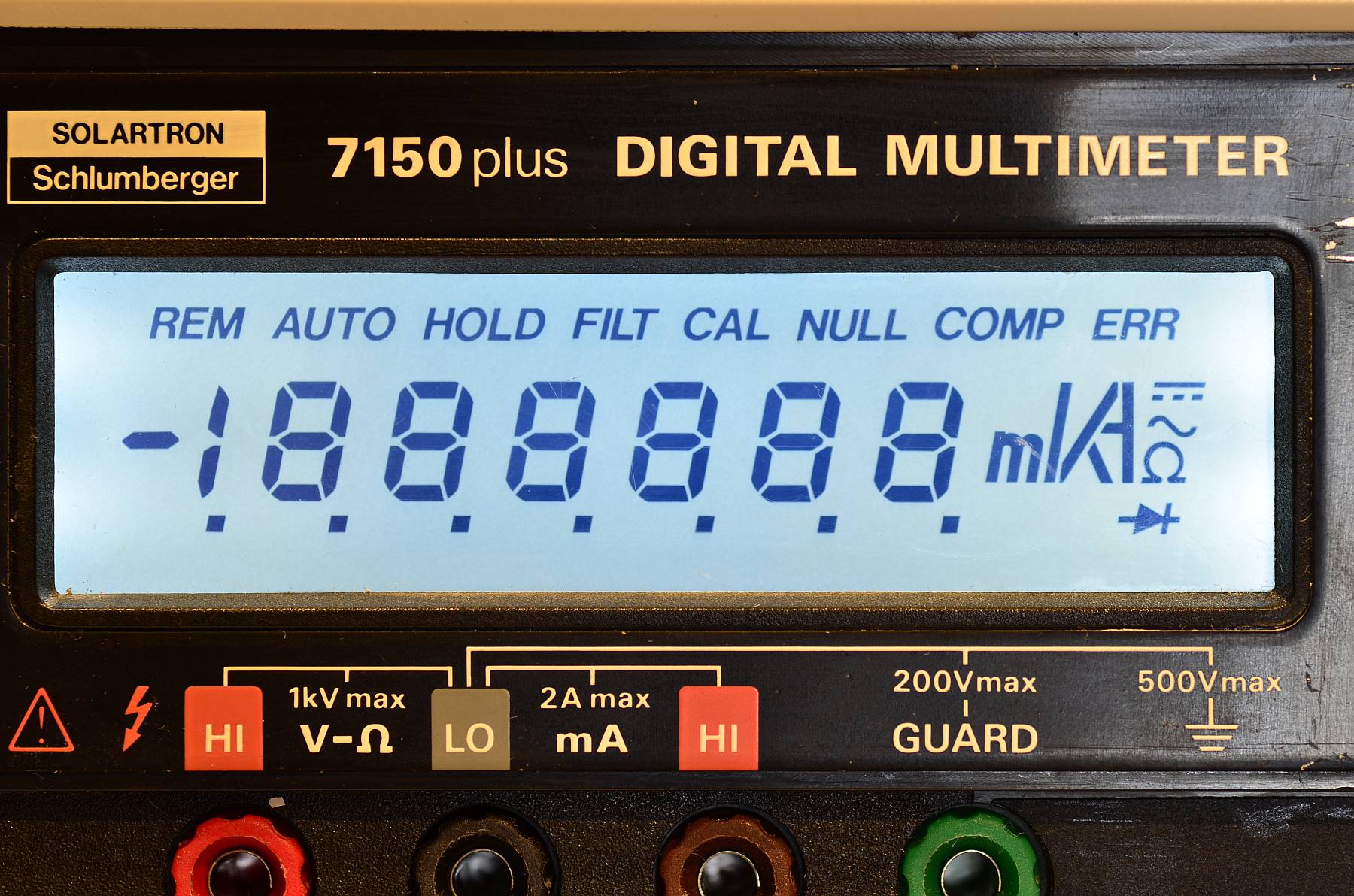
Power-on display self test
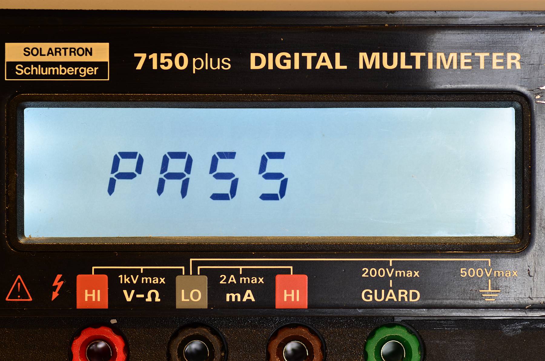
Power-on self test passed
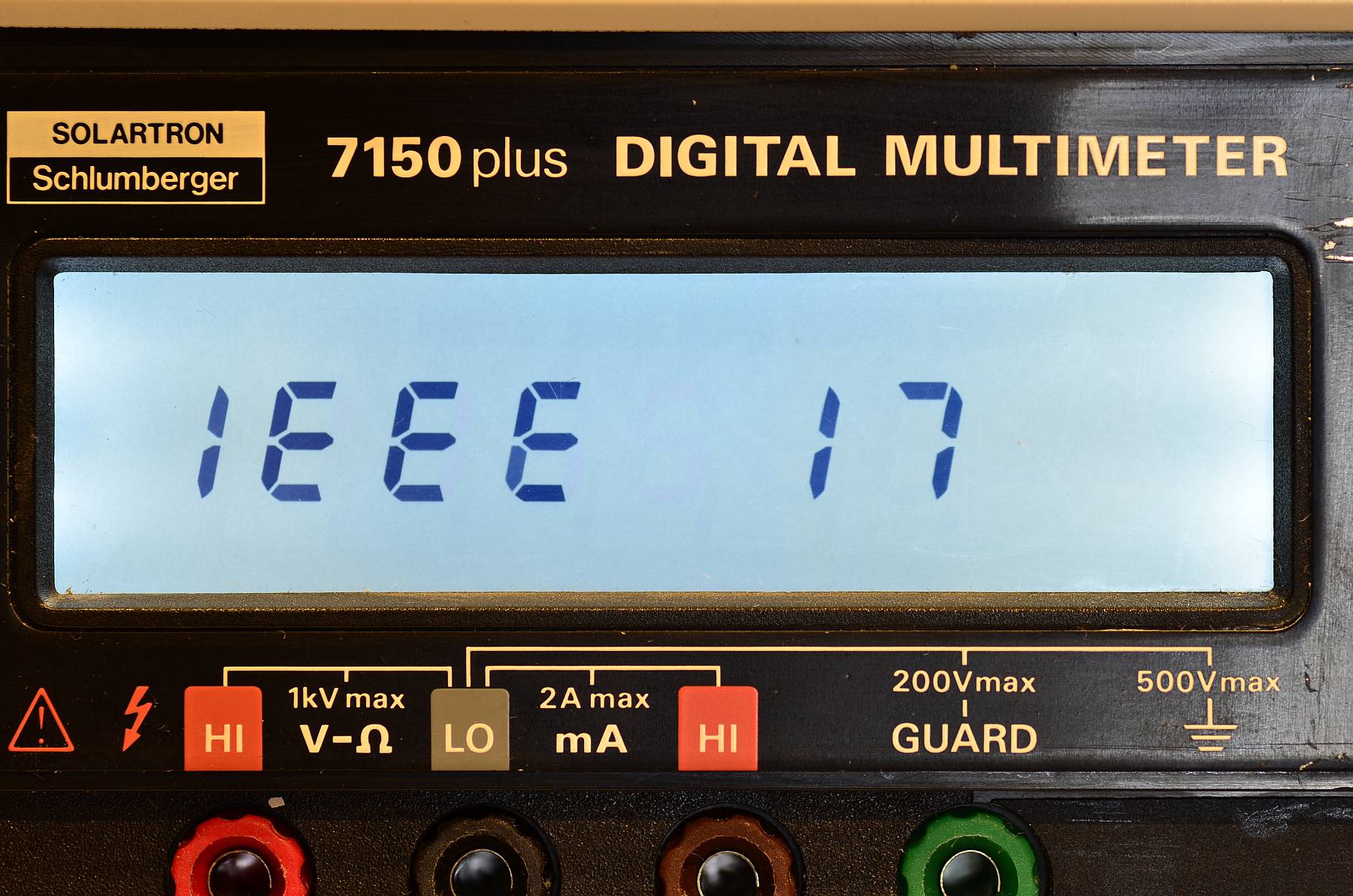
IEEE Bus address displayed after power-up
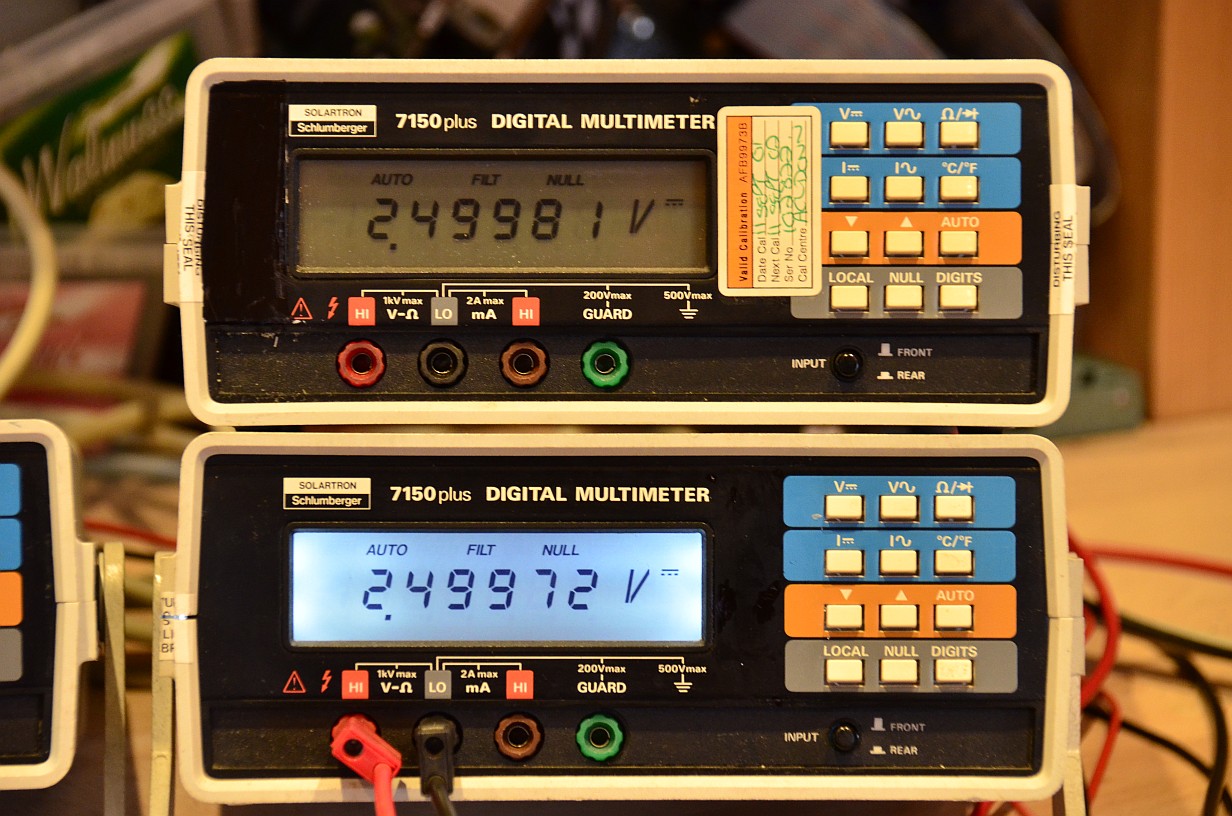
The comparison speaks for itself!